Since my other thread got hijacked, I started a new one. This is the photo diary of my coil loaded dipole build. The plan is for it to be resonant on 40/80m, fed with 450 ohm ladder line so it will tune easily on higher bands. I'm trying to only use whatever materials I can find around the house or get donated from neighbors. If I don't have something necessary, I'll purchase the most cost effective solution. Any comments, questions, suggestions, hints, tips, criticisms, are welcome, but please keep the thread on topic.

You are using an out of date browser. It may not display this or other websites correctly.
You should upgrade or use an alternative browser.
You should upgrade or use an alternative browser.
-
You can now help support WorldwideDX when you shop on Amazon at no additional cost to you! Simply follow this Shop on Amazon link first and a portion of any purchase is sent to WorldwideDX to help with site costs.
Coil Loaded Dipole build - photo diary
- Thread starter Moleculo
- Start date
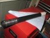
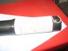
Step 1 - Make the coils.
I admit that I'm cheating. I don't have time for all the math required to build the coils precisely. Actually, I started doing the math but realized that since my primary goal was to use whatever materials I already had or were available cheaply, that the math was a luxury.
So I decided to cheat by copying an Alpha Delta DX-CC as closely as possible while utilizing the knowledge I already possess. That means that this antenna build is going to involve some trial and error which I hope to document in this thread as I go.
I measured the coil form diameter from the Alpha Delta then counted the coils. I can't tell what guage wire they use on the coils, but it's pretty small. I guessed it was probably 24ga or smaller. The outside diameter on the coil form looks to be 1.75"
I found that all my PVC is sprinkler stuff and is 3/4" max. A trip to Home Depot down the street led me to a piece of small 1 3/4" PVC for $2.00 (and change). After measuring, I find that the PVC I purchased is actually 1 7/8" outside diameter. Close enough for me. The number of turns on the Alpha Delta DX-CC coil is 68 by my count.
I have a bunch of scrap wire but a lot of the small stuff is too flexible to hold a coil form without a lot of trouble. I found a spool of solid, jacketed wire that looks about 24ga (it might be a little smaller) that is actually a pair for speakers or whatever. I pulled the pair apart so I could use each wire seperately. I didn't have enough stainless hardware, so I bought some stainless machine bolts, nuts, washers, etc for the coils. Total cost $4.00. I drilled a hole on each side of the PVC and inserted the bolt to hold the start of the coil. It turns out that I only have enough wire for 65 turns. Hopefully since the PVC I'm using is a little larger than the Alpha Delta, the 3 fewer turns in the coil won't matter much. Of course this depends greatly on the diameter of the wire in use which I'm not sure about.....
Here are the first pics. On the coil I used electrical tape on one side instead of drilling and securing with machine bolts. I'll use it this way to test just in case I need to add more turns on the coils. I'll have to cut the PVC in half in the next step.
Attachments
Here is one off of their website. I'll take a beter one this weekend and post it:
 http://www.alphadeltacom.com/graphics/test-antenna-12b.jpg
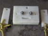
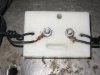
I found some thick plastic/nylon type of material on my bench. I'm not sure what this stuff is, but it's pretty strong. I think it was being used as a spacer in something that I disassembled a long time ago. I cut two pieces off the end to use for end insulators and then drilled a bunch of holes for the ropes, wires, etc. in the three pieces. I put a couple of bolts in to attach wire and ladder line to and made a simple strain relief with a dremmel tool. Cost of all this stuff: free.
Now I need to cut the PVC in half and drill a couple more holes in that for the remaining bolts and also for wire to attach to. Also time to see what wire I have.
Now I need to cut the PVC in half and drill a couple more holes in that for the remaining bolts and also for wire to attach to. Also time to see what wire I have.
Attachments
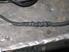
I found some wire in the garage. Unfortunately it was in four peices. One piece was about 40' long which is good. I had to twist the other three pieces together, solder them and cover with heat shrink. Now I have two legs of 40' that I can cut down to the proper lengths.
Attachments
Doc sent this to me in a PM, but it's on topic so I figured I'd post it. I hope you don't mind Doc...
I'm sure you already know it from playing with the formula, but the larger the diameter of the coil the less number of turns needed for the same inductance. The greater the distance between coils turns, the less chance of arching given a particular amount of current flow. And the larger the wire used the more area that will be adjacent to the the next coil turn, the more capacitance between turns. Not all that much of a biggy, but present. That larger wire also means more current carrying capacity. All things considered, your coils ought'a be at least 'ball-park'ish' comparable to 'Alpha-Delta's.
A little adusting of the wire segments after the coils ought'a get it resonant on 80m, or the lowest band of use.
Another way of looking at it is that since it's a multi-band antenna, and since the typical tuner will have more ability to 'shorten' an antenna than lengthen one (more inductance for lengthening one, more capacitance for shortening one), typically more capacitor size than inductor size, a larger loading coil than needed in the antenna is 'better' than one(s) too short. (Hows that for confusing logic?)
It sounds like it ought'a work. I'm interested in how it turns out.
- 'Doc
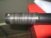
I had some time today since I couldn't find any bars showing my Raiders getting their butts kicked by the Ravens so I worked on the antenna a little more. I cut the PVC and drilled the remaining holes and assembled the rest of the hardware. When I stripped some of the coil wire I saw that that wire was a smaller diameter than I thought. I was fooled by the size of the insulation! Well, that means it might actually be closer in size to the antenna I patterned this after. Since the insulation is so much thicker, that means the spacing between wires is going to be a little more than there's also. Well, I guess we'll find out how much of a difference it makes, but I don't think I'll really care since I can just adjust the tag ends after the coil.
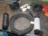
Next I measured out the wire and attached it to the PVC. The math says for an Inverted V for 7mhz it should be about 32.5 feet. So I cut each one 33'. In retrospect, I wish I had left a little more to play with just in case. What's odd is that I calculated that the 40m segments on Alpha Delta's antenna are about 35'. I got to this number by taking their stated overall length of 82', then subtracting what I physically measured as the 80m tag + coil length. Take off a few inches for the center insulator and you come up with 35'. I can't explain an extra 2' unless it has something to do with the coil. If I end up needing 2' more on each leg, I'll have to solder some back on .
.
You can see in the attached pic that I didn't attach the wire to the coil itself, just the PVC for now. I want to take a measurement of the wire by itself, then attach the coil and see what affect it has on 40m. Then I'll attach the tag ends of the wire and see what that does also.
The rest of the afternoon was spent wasting a lot of time with stuff that didn't work. I thought it would be a good idea to use some sort of glue to keep the coil wire from moving around or accidentally getting abused, I got out some contact cement glue and brushed each coil liberally with it. Nice idea except that I found out that the contact cement never really hardens up like some glues. After the dry time elapsed, I still found it to be nice and tacky. Yuck! :thumbdown: So out came the adhesive cleaner and I had to soak the coils to get the glue off. Some gently rubbing and wiping got it all back off after about 20 minutes.
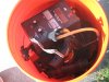
Next I got all my tools and stuff and put it in the bucket to head across the street to the park to try this antenna out. Photo of bucket of antenna stuff attached. (BTW, whoever swiped my good pair of dykes and good needle-nosed pliers, please put them back in my tool box!! :glare: ) I found the only tree that looked like it might work and got out the home-made fishing reel slingshot, took a couple of shots into the tree to get the distance down and also get it where I wanted. Then I got the perfect shot over the branch I wanted, but the lead sinker broke off on the tree and went flying off the swivel-snap, fishing line falling down. Oh well. So I attached some 100 pound dacron line to a tent post and threw it up into the tree. That worked after a couple of tries. I raised up the antenna using the dacron, answered the same question about 3 times to passer-bys about what I was doing and tied it off to the bucket to hold it. After uncoiling the wire I realized that the tree wasn't tall enough. DOH! I packed everything up and came back home after an hour of messing around in the park. Now I have to find a bigger tree.
Next I measured out the wire and attached it to the PVC. The math says for an Inverted V for 7mhz it should be about 32.5 feet. So I cut each one 33'. In retrospect, I wish I had left a little more to play with just in case. What's odd is that I calculated that the 40m segments on Alpha Delta's antenna are about 35'. I got to this number by taking their stated overall length of 82', then subtracting what I physically measured as the 80m tag + coil length. Take off a few inches for the center insulator and you come up with 35'. I can't explain an extra 2' unless it has something to do with the coil. If I end up needing 2' more on each leg, I'll have to solder some back on
. You can see in the attached pic that I didn't attach the wire to the coil itself, just the PVC for now. I want to take a measurement of the wire by itself, then attach the coil and see what affect it has on 40m. Then I'll attach the tag ends of the wire and see what that does also.
The rest of the afternoon was spent wasting a lot of time with stuff that didn't work. I thought it would be a good idea to use some sort of glue to keep the coil wire from moving around or accidentally getting abused, I got out some contact cement glue and brushed each coil liberally with it. Nice idea except that I found out that the contact cement never really hardens up like some glues. After the dry time elapsed, I still found it to be nice and tacky. Yuck! :thumbdown: So out came the adhesive cleaner and I had to soak the coils to get the glue off. Some gently rubbing and wiping got it all back off after about 20 minutes.
Next I got all my tools and stuff and put it in the bucket to head across the street to the park to try this antenna out. Photo of bucket of antenna stuff attached. (BTW, whoever swiped my good pair of dykes and good needle-nosed pliers, please put them back in my tool box!! :glare: ) I found the only tree that looked like it might work and got out the home-made fishing reel slingshot, took a couple of shots into the tree to get the distance down and also get it where I wanted. Then I got the perfect shot over the branch I wanted, but the lead sinker broke off on the tree and went flying off the swivel-snap, fishing line falling down.
Oh well. So I attached some 100 pound dacron line to a tent post and threw it up into the tree. That worked after a couple of tries. I raised up the antenna using the dacron, answered the same question about 3 times to passer-bys about what I was doing and tied it off to the bucket to hold it. After uncoiling the wire I realized that the tree wasn't tall enough. DOH! I packed everything up and came back home after an hour of messing around in the park. Now I have to find a bigger tree. Attachments
Hello Mole:
I have one of those Alpha Delta Dipole Antennas; it covers 80, 40, 20, 15 and 10 meters, or better put it’s supposed to cover those bands.
I made a 1 to 1 Current Balun to feed the Alpha Delta Antenna, 8 or 9 turns or paired 12 gauge wire around a 2.4 inch Toroid Core from Amidon. I think this throw off the dipole design from the manufacture. As I needed to tune this dipole antenna for 20, 15 and 10 meters.
The original coil inductance can be measured on your MFJ Antenna Analyzer, just set the frequency to 80 or 40 meter band and duplicate the new coils measurement in uH.
Connect the coil leads to the anaylzer SO-239 and be Xl mode.
Or figure the original coils inductance in uH from a Coil Calculator from a search engine. Then make the new coils to have the same analytical uH as the original coils.
Anyway sounds like you are having fun with experimenting around and a walk to the park.
I noticed that the 40 meter band was very broad banded, and worked well. 80 worked ok, but the other bands I had to tune. Like to hear your results when done.
My antenna easily took 1000 watts PEP without catching fire.
Jay in the Mojave
The original coil inductance can be measured on your MFJ Antenna Analyzer, just set the frequency to 80 or 40 meter band and duplicate the new coils measurement in uH.
Connect the coil leads to the anaylzer SO-239 and be Xl mode.
That's a good idea...I never thought of that. I wonder if anyone has the inductance of the Alpha Delta coil published? If not, I suppose I'll have to get on the roof and measure mine (after disconnecting the wires, of course).
BTW I was able to get my Alpha-Delta DX-CC to have very good, if not perfect SWR on each of the bands it is made for but it took some time messing with the wire lengths. I've run as much as 2+ KW through mine on the higher 75m frequencies (actually MARS) with no problems!
I found this link today which is the same project with slightly different dimensions. It's a good read:
Coil loading of an 80m dipole for restricted space
Coil loading of an 80m dipole for restricted space
Yo Mole:
Yeah ok good deal, great info there. I have built a 80, 40 20, 15, and 10 meter dipole all with seperate lengths for the bands, but haven't had the time to put it up, and tune it.
I am also thinking of a remote automatic tuner in the Barn to tune a long dipole antenna having the tuner do all the work after programming in all the bands so the tuner will slam there real quickly and handle all the power. But at around a grand plus for the tuner you would be able to have a effictive dipole. See:
Welcome to Palstar.com Model AT Auto 1500
But that wouldn't allow you to experment with the tuning of the dipole. 2000 watts+, you city people run a lot of stream as compared to us poorer folk who live on dirt roads and in the Desert! Hahahhahaha
Jay in the Mojave
Hello All:
Ok I posted this yesterday but the computer out smarted me again, and it didn't get posted!
The Alpha Delta Dipole Antenna has a real great performance on the 40 meter band. That is, it has a wider that normal bandwidth and works well. I believe the 40 meter wider bandwidth is due to the coil on the end of the dipole antenna length for 40 meters, seeing a inductive reactance.
This can be verified or not verified by making a dipole antenna that has the coils for a dipole antenna for 160/80 meters, or even 40/20 meters. Food for thought here.
If this is true then one might want to make a 160/80 meter dipole antenna that worked somewhat on 160 meters, but had a very wide SWR Bandwidth on 80 meters.
Your comments....
Jay in the Mojave
Jay,
"I believe the 40 meter wider bandwidth is due to the coil on the end of the dipole antenna length for 40 meters, seeing a inductive reactance."
I'm afraid not. That coil is a loading coil for 80 meters, has nothing to do with the 40 meter antenna which is located below the 80 meter antenna. I think if you measured that wire segment below the segment with the coil in it, you'll find that it's for 40 meters. (That's going only by the posted picture of the 'Alpha-Delta' antenna, don't have one so can't do that measuring myself.)
The bandwidth of that 40 meter antenna is sort of typical, not really all that extraordinary.
Now, if that loading coil was a 'trap'... but it isn't.
- 'Doc