
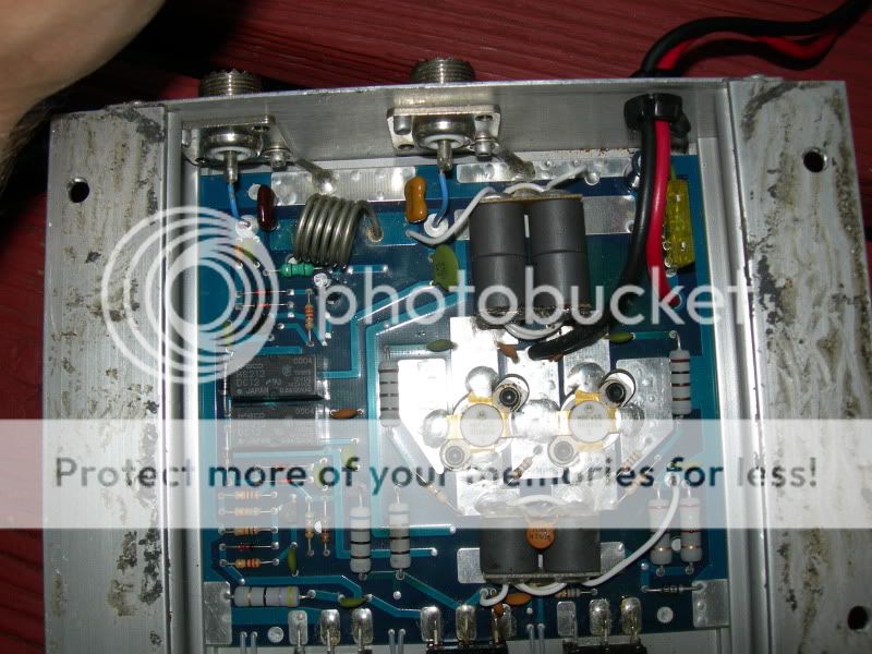
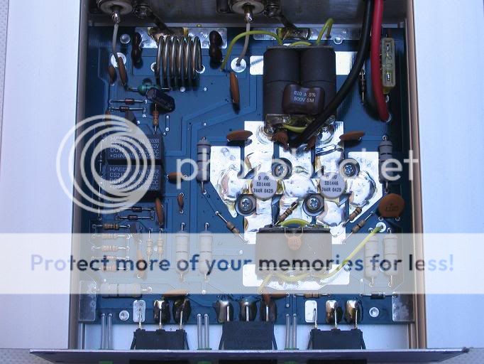
I have a Galaxy 225 Amp that is an EXACT copy of a Palomar 225, blue face. I picked it up used at a cb shop for 50 bucks, the owner said it didn't have full output power. It seems to be a pretty sturdy little amp, but the problem is that it only puts out about 50 watts.
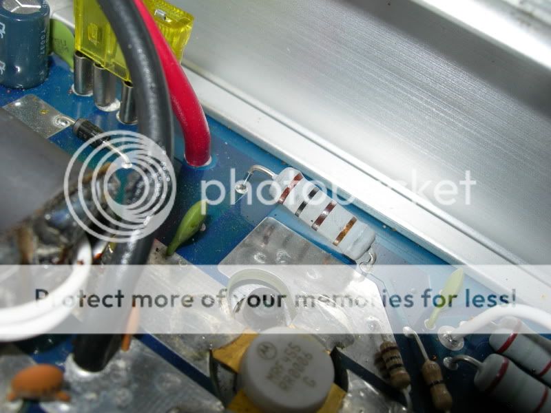
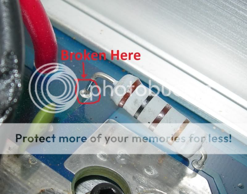
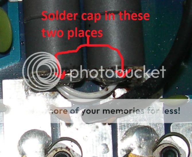
When I inspected it, I found a resistor that has broken one leg off of its solder joint, the rest of the amp seems fine. The pre amp works amazingly and the first radio check I requested got me a "you sound somewhat scratchy" but that was with a cheapo mag mount antenna on my truck and the reply was from another CBer 41 miles away in the woods!
Its my first amp and though it works great already I just want to get all the power out of it.
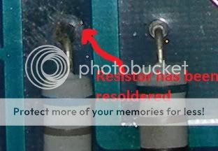
There is another resistor on the board that broke in the same spot that has been fixed by the previous owner. It seems he didnt even remove the board from the chassis and just put new solder on one leg of the resistor and connected it right to the board.
I have tried to remove the board but it seems to be impossible without desoldering the front switches and drilling out the rivits that hold the SO 259 connectors to the chassis. I tried to remove the four screws that hold on the faceplate, but it still was connected to the frame somehow.
My question is how can I remove the board from the chassis to solder the leg back on? Also, could I just patch it the way the previous owner did and not have to remove it?
I know that boards have a solder side and a component side but it seems that the pathways on the board are on the component side as well and the components are just soldered to parts of exposed pathways on the component side. If this is the case, I should be able to get away with just soldering the resistor back on the component side right?
Its my first amp and I'm really looking forward to a response so I can get this guy up and running and make contacts from 82 miles away!!!
I have added a few pictures to help everyone get a better idea of what's going on. The second and third pictures are of the broken resistor and the fourth is of the broken resistor that was fixed by the previous owner.

When I inspected it, I found a resistor that has broken one leg off of its solder joint, the rest of the amp seems fine. The pre amp works amazingly and the first radio check I requested got me a "you sound somewhat scratchy" but that was with a cheapo mag mount antenna on my truck and the reply was from another CBer 41 miles away in the woods!
Its my first amp and though it works great already I just want to get all the power out of it.
There is another resistor on the board that broke in the same spot that has been fixed by the previous owner. It seems he didnt even remove the board from the chassis and just put new solder on one leg of the resistor and connected it right to the board.
I have tried to remove the board but it seems to be impossible without desoldering the front switches and drilling out the rivits that hold the SO 259 connectors to the chassis. I tried to remove the four screws that hold on the faceplate, but it still was connected to the frame somehow.
My question is how can I remove the board from the chassis to solder the leg back on? Also, could I just patch it the way the previous owner did and not have to remove it?
I know that boards have a solder side and a component side but it seems that the pathways on the board are on the component side as well and the components are just soldered to parts of exposed pathways on the component side. If this is the case, I should be able to get away with just soldering the resistor back on the component side right?
Its my first amp and I'm really looking forward to a response so I can get this guy up and running and make contacts from 82 miles away!!!
I have added a few pictures to help everyone get a better idea of what's going on. The second and third pictures are of the broken resistor and the fourth is of the broken resistor that was fixed by the previous owner.


")