• You can now help support WorldwideDX when you shop on Amazon at no additional cost to you! Simply follow this Shop on Amazon link first and a portion of any purchase is sent to WorldwideDX to help with site costs.

Elecraft K3 Build Photo Diary

Moleculo

Ham Radio Nerd
Apr 14, 2002
9,199
1,684
283
I received my Elecraft K3/100 and started the build process this weekend. As I go, I'm taking pictures of the major steps so everyone can follow along with me. Anyone who has also completed this project is welcome to join in and comment. Tips are appreciated!

Enjoy and participate in the project with me!


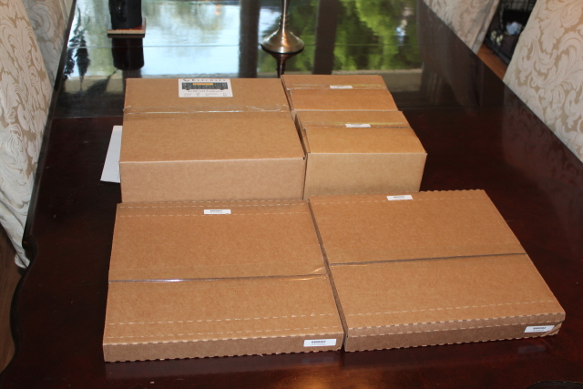
I first opened the shipping box and set out all of the smaller included boxes. Everything I ordered is in here:

1316-1280777977-33b76041624b9a811ed1c105479ca463.jpg


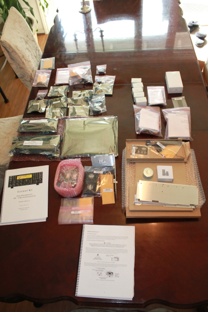
Unpacking the boxes to reveal the contents inside:

1317-1280777977-7c3993b2d1c30ac3f18cf17221e6ec90.jpg


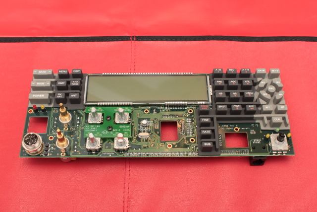
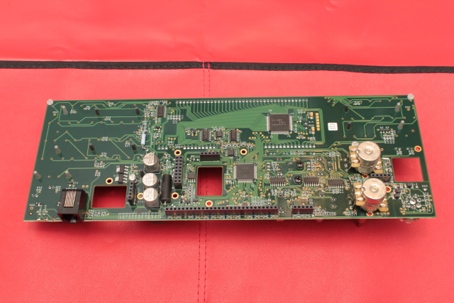
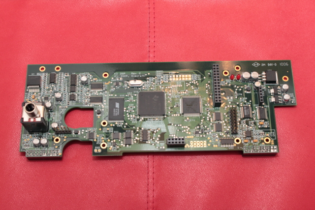
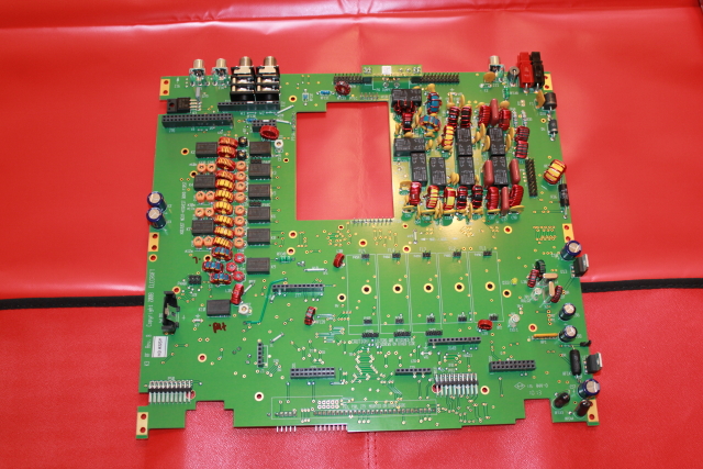
Here is the main RF board where the K3 will be built up from:

1318-1280777977-dade68bebef94c4944e8812efe816662.jpg


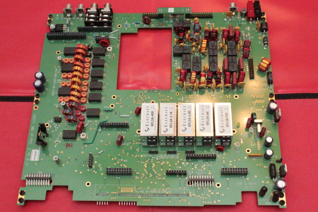
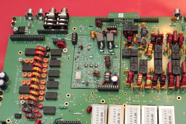
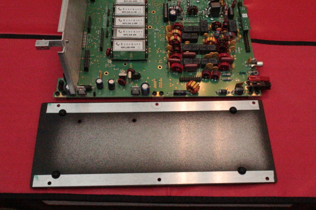
Mounting hardware installed on the board and all of the filters I purchased populated. You install the filters in order of bandwidth from right to left, with the right side staring with the widest.

1319-1280777977-0d30c89721be41c3fa35cbce5bf2b332.jpg


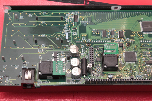
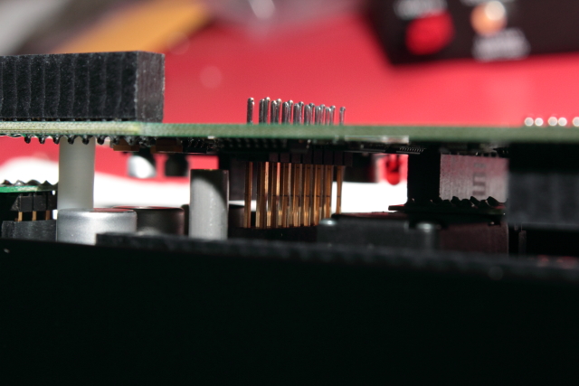
Low Power Amplifier mounted where the hole in the board was. Note the 3 connecting blocks on the top, bottom, and left side of the board.

1320-1280778064-461c900c1b71b2149486d9aa8f29ff92.jpg


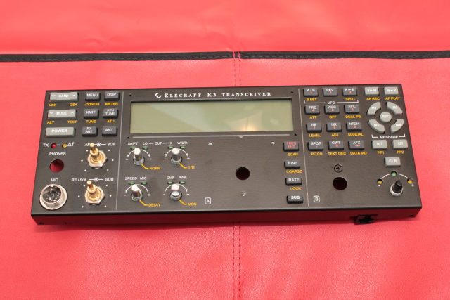
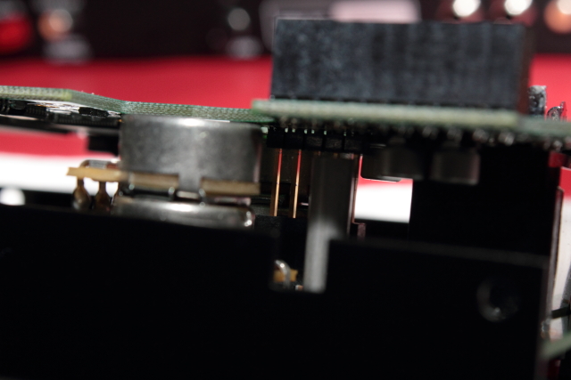
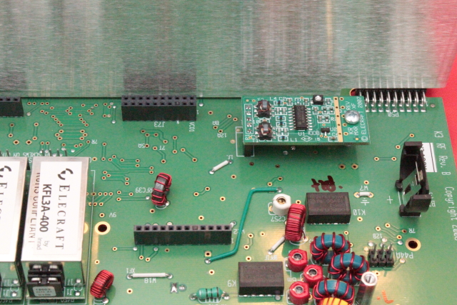
Front panel shield and mixer board mounted:

1321-1280778064-ce8f370b0766fa579b313d024d4ea7c0.jpg


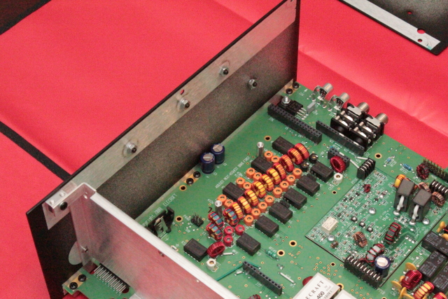
Left panel mounted. The screw holes at top are where the 2 meter module would go if I had ordered it.

1322-1280778064-2675d75204a05d57be7a7d288a933b1f.jpg


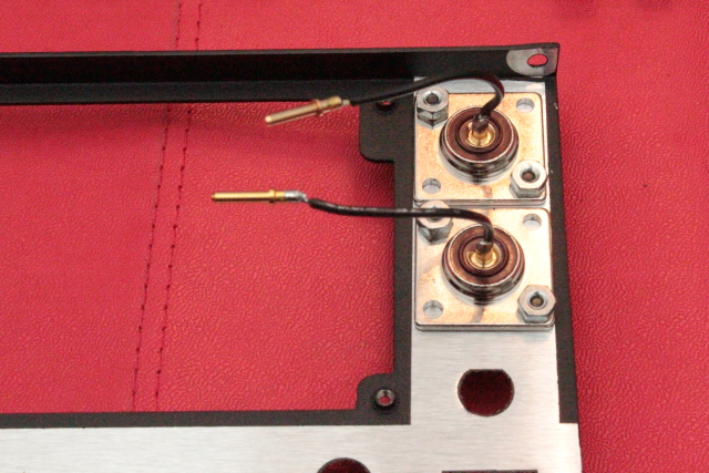
Installing the SO-239 connectors on the rear panel. Note the plugs already attached to the end of the coax.

1323-1280778064-c9163589dee285387f52448bdc359eed.jpg


Preparing the right panel. In this step you also mount the rubber feet which you can see poking through the big holes. These are pretty difficult to get in. The manual says to use a little soap to help you get the rubber foot through the chassis, but I found that a little water soluble "personal lubricant" worked better :eek:hmy:.

1324-1280778260-03d85b791145869acebfce2244e0c9c6.jpg


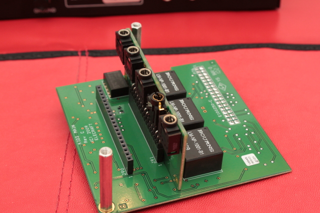
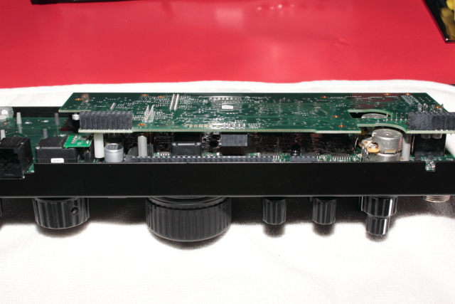
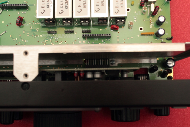
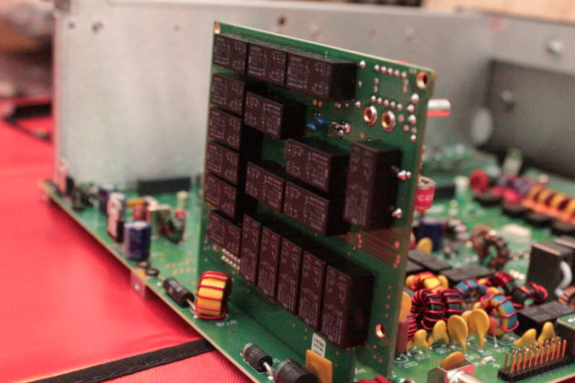
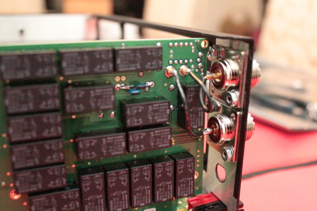
Mounting the optional antenna tuner. Here is the relay side of the board:

1325-1280778260-a6d4dfef04a7668b90fe8fd0aa133cbb.jpg


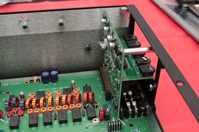
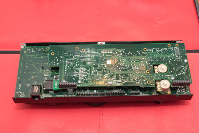
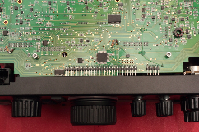
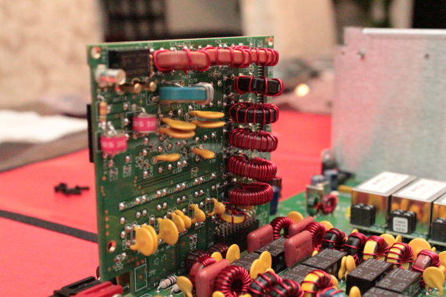
And here is the capacitor and inductor side of the tuner board:

1326-1280778260-467593e0cfa19548ea87963207dd8ae3.jpg


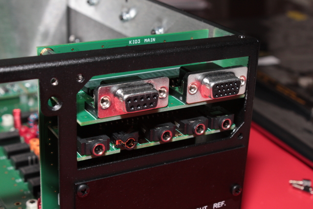
The back panel is now mounted:

1327-1280778260-be99b83f73b44eddc9132dcf4c8665ea.jpg


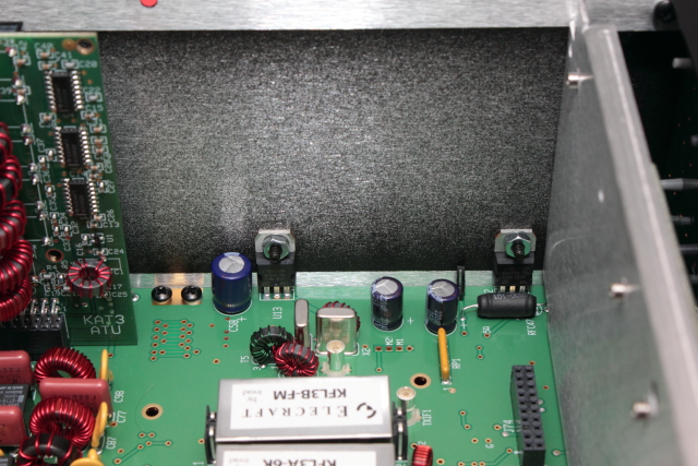
Plug the antenna wires into the jacks on the tuner board:

1328-1280778404-0287bb22c1cdefe871ccdc605c725789.jpg


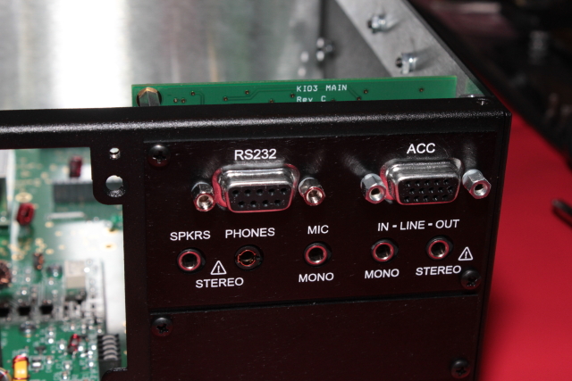
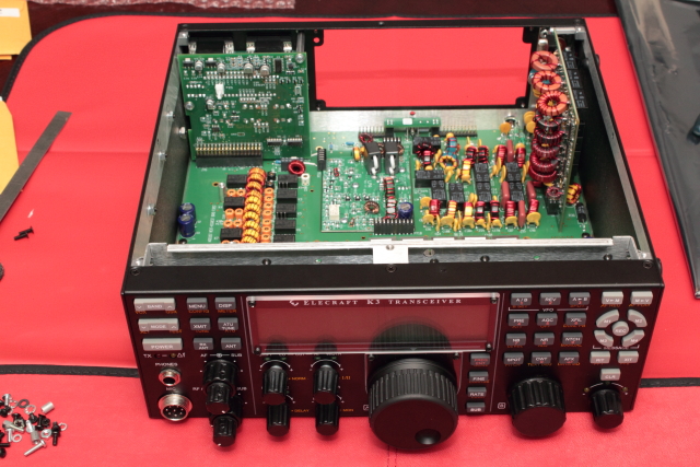
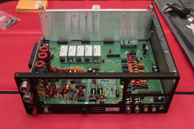
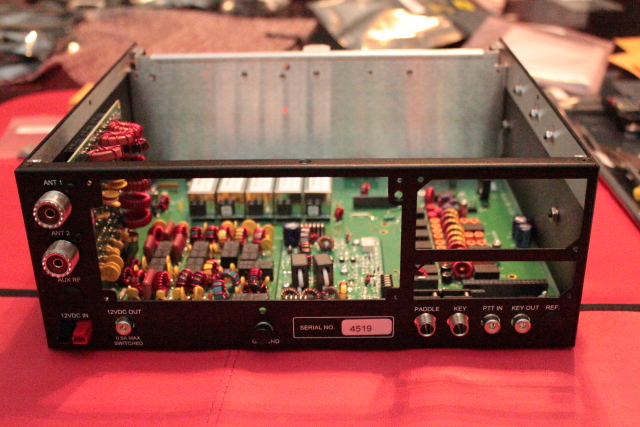
The right panel is now mounted and the main chassis is essential assembled:

1329-1280778404-d6d5ecb3a6c39f49b4ad558ab70c2c7b.jpg
 

It's like Christmas in august
Just pay attention to the screw lengths and sort accordingly.According to my friend at elecraft people not paying attention to this is one of the main (if not only) way to fudge up the Build (cracked boards missing screws Etc.)Have fun.i'll be watching:pop:
 
Yeah my wife is letting me use the dining room table. Of course she complained and wanted me to use a small table in my den, but after she saw all the parts laid out, she understood why I wanted to use the big table. Despite the complaining, she's a good sport about it.

And yes, you get to assemble it. If you want a fully assembled unit, you can purchase that for a couple hundred extra bucks, but why miss out on all the fun? You don't do any soldering but there is still plenty of work to do.
 
Here are the next series of steps in the build. Keep in mind that I'm showing the major steps, but there are a lot of small assembly steps that involve attaching mounting hardware, posts, etc. Basically anything that you see in the picture that has a screw, nut, or post is something you have to do yourself.

This is the Main I/O board on the bottom with the Audio I/O vertically that I've already attached:

1330-1280855470-b8338cd8cff62c193ae066037ef048a0.jpg


The main I/O board attaches vertically to the left rear (right side if the back is facing you). Note that in this picture the screws on the main I/O board holding the posts on are the wrong ones. I realized that they were wrong after I took the pic and corrected it. It didn't really matter in this instance, but it usually does, so I wanted it to be correct.

1331-1280855470-4d07f6c1e0753e9bf5be07a13bced9bf.jpg


Now the Digital I/O daughter board is attached to the main I/O board.

1332-1280855470-2b28e4e845b1511a5f33aa002cb7950f.jpg


Attach the panel cover with the labels and you can now tell what these ports are all for.

1333-1280855470-4076bbf49314f25ec906326d8a3672a0.jpg


Here's the front panel taken from the package:

1335-1280855564-691e13ad444e356254d619b13478eecd.jpg


And the backside of the front panel. Note the cut-outs in the board where things will be installed:

1334-1280855564-136bb6691b637d6fb93cd34156de93d5.jpg


Assemble all the mounting hardware on the board (there is a bunch of it) and attach the front face:

1336-1280855564-9473d23eee259f70f830206c880c4f4c.jpg


This is the point where the two VFO encoders get installed into two of the cut-outs I mentioned before:

1337-1280855564-af7f5ca9ff0d5601c480fcf2306c40ff.jpg


The VFO encoders shown from the front with the mounting hardware attached and many fingerprints on the front panel :D:

1338-1280855801-a060adae222f371a6efacdccc22374a7.jpg


The front trim panels get attached next. Before you do this step you have to thread the main display panel screw holes. You actually do that before you attach anything to the main panel. You have to attach these trim panels very carefully or you will crack them.

1339-1280855801-1ee86529e499d2c4f5f777c625e42e68.jpg


I'll assemble a little each night and continue the pics throughout the week, so stay tuned...
 
I worked on it a little more tonight, so here are the updates:

The knobs get installed next. For the most part, this is fairly straight forward, although the instructions in the manual make the double left knobs more complicated than it needs to be. I followed the manual's instructions for the first bottom right set, then did it my own way for the second, top left set. Basically, you have to get the knobs attached in a way that prevents the top two knobs from binding on each other while still allowing them to spin freely. It's a lot easier to just figure it out and do it yourself, IMO.

1340-1280904575-3754ec8d6e76808ed41d8ba2e0cbe897.jpg


This is the DSP board. It gets attached to the back of the display panel.

1341-1280904575-15a9e50abf607bfce6590867419189fb.jpg


When you attach the DSP to the main display board, you have to do it very carefully. On the underside are two pin blocks that must be perfectly aligned to make this work. Here are a couple of pics that show you the pins on the DSP board (gold color) attempting to be aligned and set on the back of the radios' main display board

One side of the DSP board pins aligning up with the main RF board. You have to align the gold colored pins on the underneath side.

1343-1280904575-63fcf44de4136e0b290642d33006cde5.jpg


Other side that needs to be mated to the main board. The pins are in the very middle and hard to see:

1342-1280904575-dda53b1e9b57790f0c0038f169318f8a.jpg


The DSP board lined up and ready to be locked down:

1344-1280904721-6ec19486d9e58a0218b68a88bff22fd2.jpg


Here is the completed front display with DSP board attached:

1345-1280904721-4f3375c43b9d4c41db862ed04b474e41.jpg


Next, we mount the front panel & display to the main board. This step sounds really simple, but it is not. The instructions tell you to remove both side covers to make this easier. I tried removing only the one side cover and wasted about half an hour trying to get the boards to align before I reread the instructions and saw that you need to remove both.

When you attach the front panel, you need to be able to see all of the connectors to ensure they are mated properly. Look below the main RF board and the to right of the aluminum tab to see the pins that you need to align between the panel and the main board. There are others on the left side (not shown) that need to be mated, as well.

1347-1280904721-7b8a17be3e0b8e8a74f22abf4715deb8.jpg


Here are pins on the bottom side of the main RF board and face that you align. These are easier to see:

1346-1280904721-446ec5af150f3e701babfec461f6f98d.jpg


Next, we secure the voltage regulators to the main chassis.

1348-1280904902-f75ae39f4bf217f4ccfad6448ed6c84c.jpg


Here is the rig with all the covers and face attached.

1349-1280904902-28171f78281c767ed18e8c1c60362cad.jpg


As you can see, it's coming along. Next, we plug it in, fire it up and perform the smoke test.
 
WOW(y) that is a pretty neat rig Moleculo. I wish they would do soething like that with cb's I'd buy one just for the fact you can say " hey i put this thing together".

For the dual knobs did they not come with a little teflon washer, and if not what did you do differently from what the instructions described to make it easier to put together and not bind on each other?

Someone really needs to come up with a DIY CB with quality part's as it might spark more intrest into the radio hobby.

Moleculo you're going to have to do a video review after it is all put together.

Heath Kit used to cell all sorts of kits for the consumer to build who had moderate soldering skills and limited knowledge of electronics and it would be nice if there were a company step up and try that again as it would most likely lead to more amateur interest in radio.

I sorted tons of resistors and capacitors for the SB-220's when my dad built them back in the day.
 
I cant believe it is taking him this long to build it, I wouldnt be able to stand it and would work straight through till it was finished hehehehe ..
 
For the dual knobs did they not come with a little teflon washer, and if not what did you do differently from what the instructions described to make it easier to put together and not bind on each other?


No, the teflon washer probably would have made it a little quicker. What you have to do is space the bottom dial so it is not resting on the front panel, then attach the top dial so it is not resting on the bottom dial. There are a couple of little alan screws to tighten it up. The manual has you place the bottom one on loose, then attach the top knob, tighten the top, then tighten the bottom by lifting it slightly off the face plate. The problem with that is if you put the top knob on too deep, you'll never get them set so that they don't bind. What I ended up doing is just set the bottom knob, tighten it up so it turned freely, then placed the top knob, tightening it up so it turned free. It's really simple when you do it that way and wastes a lot less time.
 
After completing this part of the build and before performing the smoke test, you have to do some resistance checks. I didn't take pictures of this step, but I'll give you a few tips on this step.

There are four places that you need to check before powering it on. The first place you check is the power connector. Depending on your DMM, you may have a difficult time getting a reading by putting the probes into the Anderson Power Pole connector. This was the case for me, but simply flipping the rig over and testing the solder pads where the power connector is attached through the bottom of the board worked fine.

The other check that may give you some difficulty is the Voltage regulator labeled U12. It is the one on the right side in this pic:

1348-1280904902-f75ae39f4bf217f4ccfad6448ed6c84c.jpg


You're supposed to get a reading greater than 500 ohms. However, if your DMM presents enough voltage to the regulator, you may get strange readings which is caused by the regulator actually kicking into action. For me, the DMM briefly showed about 550 ohms but the voltage regulator quickly kicked in and it settled at about 440 ohms. Don't freak out when you see this - it's normal.
 

dxChat
Help Users
  • No one is chatting at the moment.
  • @ Wildcat27:
    Hello I have a old school 2950 receives great on all modes and transmits great on AM but no transmit on SSB. Does anyone have any idea?
  • @ ButtFuzz:
    Good evening from Sunny Salem! What’s shaking?