Well I finally decided to build an amp for a winter project. I have had a used pair of Eimac 4CX250B tubes for several years as well as a new pair of Eimacs, still in the boxes and figured it was about time to do something with them.I have plans in the future for an HF amp so I decided that this one would be built for 6m. Besides the tubes I also have a pair of Eimac SK-620 air system sockets and SK-626 ceramic chimneys I picked up at a hamfest years ago for the ridiculous price of $10.00 for the two sockets and two chimneys. Yesterday I decided to venture into the deep dark recesses of the basement and start digging out the stuff to build the power supply for the amp. The power supply will be built on a separate chassis and will be a floor model power supply.I didn't get any work done on it today other than parts placement and photos. The fridge has started acting up so the day was spent shopping for a new one. There goes a bunch more of my tower and amp money.  I got a hell of a deal on it, too good to pass up really, but anything right now is too much. Enough of the depressing stuff and on to the fun stuff.
Below is the chassis with the major components in place. The four large gray transformers will be mounted upside down from what is seen in the photo. That will actually make them right side up and the terminals will protrude down through holes in the chassis and the transformers will be bolted from the underside. There are two identical Hammond plate transformers to be wired in series. They are the largest of the transformers seen here and weigh in at 30 pounds EACH. The two smaller gray transformers on the right are identical Hammond filament transformers at 10 pounds EACH. I only need one of them but I may as well mount the other as this supply may be used in the future with other projects.The lower left is occupied by the Sprague 2500 volt 100uF filter capacitor for the high voltage. The two transformers in the middle are for the screen supply if I use it (with red plate) and bias (smallest of the two).I figure I may as well build a supply with the ability to run tetrodes and then I'll figure what I will do with the amp later that way all the work is already done.The chassis has two breakers already installed as seen below the two pilot lamps. I may use them or just leave them in for looks. I need to recheck their ratings first.Either way they look cool.
Empty chassis.

Proposed mounting configuration of major components.

A little better oblique side view of the power supply chassis.

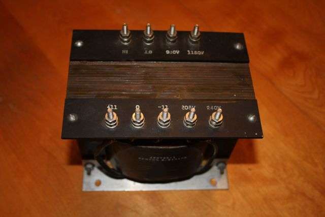
One of two plate transformers. BTW these are oil filled and no they do not leak.

The filter capacitor. This should work well and of course I will need a step start to keep the rectifiers from blowing.2000 volts into 100 uF is a LOT of inrush current.

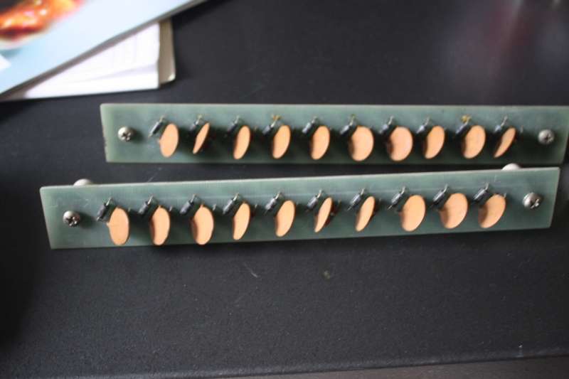
Speaking of rectifiers, here are the plate rectifiers. They will be tapped in the middle to make a full wave bridge circuit. They have ceramic mounting standoffs and were in the plate supply of the old RCA transmitter I scrapped.
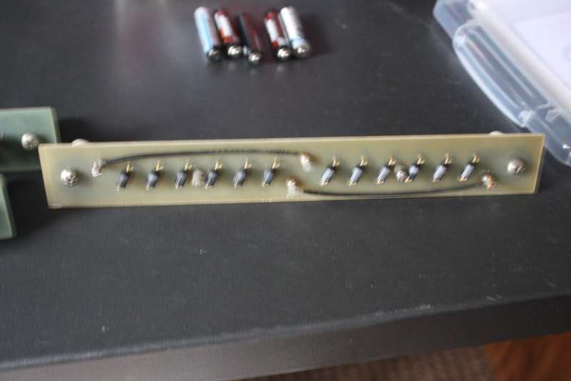
Here is the rectifier for the screen supply if used. It was in the screen supply of the old RCA transmitter. It also has ceramic standoffs for mounting. Sorry for the fuzzy image. The auto focus must have locked onto the desktop instead.
Front view of the chassis. This is all the original stuff on the front panel from when it was serving as airforce communications gear. I figure the two pilot lamps can be used for filaments on (green) and plate enabled (red). Lots of fuse holders to use and a nice looking pair of breakers. I plan to leave everything in place on the front panel whether it is used or not. It just looks cooler that way.The silver toggle switch in the lower right is for power ON while the switch under the red lamp will be used for switching the plate transformer's primaries in series or parallel in order to halve the plate voltage for tuning testing etc.

Hopefully I can get some holes drilled in the next day or two. I have a LOT to do outside in preparation for winter but it has been raining the past 4-5 days here and sure as hell now that I want to get this started the sun will shine.
The amp will be housed in this cabinet BTW.

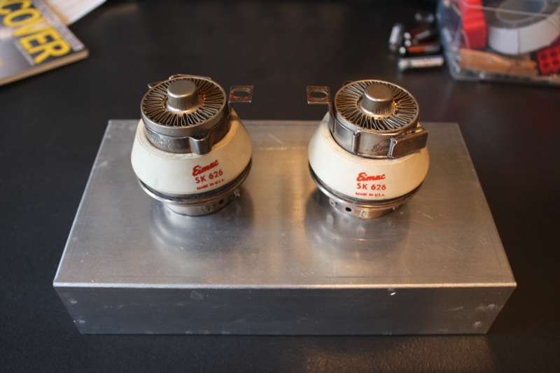
I will build a sub chassis inside the cabinet to house the tubes. It will look something like this below with the tube sockets mounted down in the aluminum chassis and pressurized from underneath with a blower.
That's all for now. More updates as work progresses but don't be impatient. I have a LOT of things to do before winter arrives. Other components like the step start relay and the plate voltage delay timer will be mounted either on the underside of the chassis or on top wherever there is room.
Oh yeah, did I mention the thing weighs in at 115 pounds as you see it now?
I got a hell of a deal on it, too good to pass up really, but anything right now is too much. Enough of the depressing stuff and on to the fun stuff.Below is the chassis with the major components in place. The four large gray transformers will be mounted upside down from what is seen in the photo. That will actually make them right side up and the terminals will protrude down through holes in the chassis and the transformers will be bolted from the underside. There are two identical Hammond plate transformers to be wired in series. They are the largest of the transformers seen here and weigh in at 30 pounds EACH. The two smaller gray transformers on the right are identical Hammond filament transformers at 10 pounds EACH. I only need one of them but I may as well mount the other as this supply may be used in the future with other projects.The lower left is occupied by the Sprague 2500 volt 100uF filter capacitor for the high voltage. The two transformers in the middle are for the screen supply if I use it (with red plate) and bias (smallest of the two).I figure I may as well build a supply with the ability to run tetrodes and then I'll figure what I will do with the amp later that way all the work is already done.The chassis has two breakers already installed as seen below the two pilot lamps. I may use them or just leave them in for looks. I need to recheck their ratings first.Either way they look cool.
Empty chassis.
Proposed mounting configuration of major components.
A little better oblique side view of the power supply chassis.
One of two plate transformers. BTW these are oil filled and no they do not leak.
The filter capacitor. This should work well and of course I will need a step start to keep the rectifiers from blowing.2000 volts into 100 uF is a LOT of inrush current.
Speaking of rectifiers, here are the plate rectifiers. They will be tapped in the middle to make a full wave bridge circuit. They have ceramic mounting standoffs and were in the plate supply of the old RCA transmitter I scrapped.
Here is the rectifier for the screen supply if used. It was in the screen supply of the old RCA transmitter. It also has ceramic standoffs for mounting. Sorry for the fuzzy image. The auto focus must have locked onto the desktop instead.
Front view of the chassis. This is all the original stuff on the front panel from when it was serving as airforce communications gear. I figure the two pilot lamps can be used for filaments on (green) and plate enabled (red). Lots of fuse holders to use and a nice looking pair of breakers. I plan to leave everything in place on the front panel whether it is used or not. It just looks cooler that way.The silver toggle switch in the lower right is for power ON while the switch under the red lamp will be used for switching the plate transformer's primaries in series or parallel in order to halve the plate voltage for tuning testing etc.
Hopefully I can get some holes drilled in the next day or two. I have a LOT to do outside in preparation for winter but it has been raining the past 4-5 days here and sure as hell now that I want to get this started the sun will shine.
The amp will be housed in this cabinet BTW.
I will build a sub chassis inside the cabinet to house the tubes. It will look something like this below with the tube sockets mounted down in the aluminum chassis and pressurized from underneath with a blower.
That's all for now. More updates as work progresses but don't be impatient. I have a LOT of things to do before winter arrives. Other components like the step start relay and the plate voltage delay timer will be mounted either on the underside of the chassis or on top wherever there is room.
Oh yeah, did I mention the thing weighs in at 115 pounds as you see it now?