• You can now help support WorldwideDX when you shop on Amazon at no additional cost to you! Simply follow this Shop on Amazon link first and a portion of any purchase is sent to WorldwideDX to help with site costs.

142GTL Final

azscr4mbl3r

Member
Dec 6, 2012
19
0
11
Hey,
I have this old (1997) 142GTL. It got it modded every possible way I think P.O. It has low power so I lifted the legs of the 1306 and 1307. The 1306 tested bad. I had a 1969 and put it in but now I have ZERO bias current. Previous owner had the voltage turned up to over 15 I backed that down to mid 13's.
I have a dvm o-scope and pace 5403a meter so I can't do everything. I have a sig. gen. OTW. No freq counter so far. :( So any where I can test to narrow it down? Modulation on the meter is good but power out is zero. It was just very low ( under a watt ) until I swapped in the 1969.

TIA!!

-Allen
 

Did the Service Bulletin #1226 to the Voltage Regulator yet? It is ESSENTIAL.

http://www.cbtricks.com/radios/cobra/142gtl/graphics/cobra_142gtl_tech_note_1226.pdf

You could have used a 2SC2166 driver in place of the 1306.
I would have.

No bias on the driver? Replace/test the MV1Y diode/biasing diode next to the driver. Check ALL components in the driver bias circuit if you must.

Sorry to hear that it has been fully modded; rare to find them unmolested any more . . .
 
  • Like
Reactions: LeapFrog
Hey Thanks! I have the bulletins I have not checked to see if they have been done. I have to tell you many of the mods were done some not so much wires twisted together and electrical tape ( LOTS OF TAPE ) used to hold them together.. One had , I kid you not RTV holding them together.. must have run out of tape... :) I worked on TV and video mostly not radios so I am learning.
Learning what the mods are so I can recognise them is one thing I am still learning. D41 was cut and tr32 removed I replaced and reconnected those. What is the purpose of that?

Crystal switch mod has these and I have no real idea what this is accomplishing?
11.2595 , 11.112 is the other the center one 10.9655 it is on a rotary type switch Radio nut has a youtube of replacing one but he never says what it is other than the obvious "crystal switch" What is that for three crystals?

Thanks for the help!! I'll let you know how it goes

Merry Xmas!

-Allen
 
It has not been done. I went ahead and checked the voltages in and out. 13 in 8 out on the three outputs. I am going to check it for the other service bulliten and then look for that diode you mentioned.

thanks,

-Allen (y)
 
Service Bulletin #1226 calls for a 18.2v zener diode; but a more common 18v zener works just fine. Done this to a few radios. It is done to save the voltage regulator from failure. The other diode in this mod is the SR1K2; just use a common 1N4001.

MOF just restored a 142 a few weeks ago. TR32 IIRC is the AM Limiter. Just as well that you replaced it; I always do. Recommend that you replace the AM Regulator; it is found in the rear right corner of the radio. It is mounted to the same aluminum wall that the audio IC and the regulator IC is found. It is too wimpy; use an NTE-152 to replace it.

Didn't know these radios were made up to '97. Thought they quit making them in the late 80's. You may well consider replacing all of the electrolytic and tantalum caps in it if it older than 20 years old. Use a higher capacity voltage rating than the OEM parts too. Especially all of the 10v caps in it if no others; use a 16v or 25v cap with the same uf value. Align the radio afterwards and she will be nearly as new.

The crystal switching in the loop osc is for obtaining another bank of 40 ch outside of the CB band for each additional crystal.
 
Last edited:
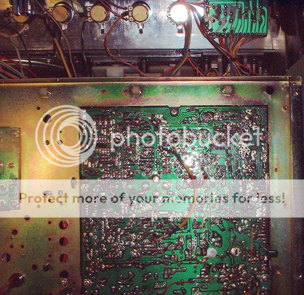
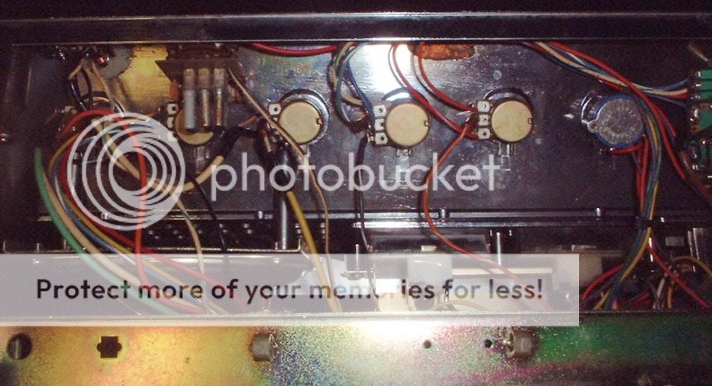
Here are some pix L-38 is the best "mod" IMHO red wire routed back around to VR7 I think is where they have it going... I hate to touch it LOL I should ohm it out just for fun...


>>>>>>>>>>>>>>>>>>>>>>>>>>>>

DSCF0003_zps3cc54bde.jpg
[/IMG]

DSCF0001_zpsc380aa4c.jpg


Service Bulletin #1226 calls for a 18.2v zener diode; but a more common 18v zener works just fine. Done this to a few radios. It is done to save the voltage regulator from failure. The other diode in this mod is the SR1K2; just use a common 1N4001.

MOF just restored a 142 a few weeks ago. TR32 IIRC is the AM Limiter. Just as well that you replaced it; I always do. Recommend that you replace the AM Regulator; it is found in the rear right corner of the radio. It is mounted to the same aluminum wall that the audio IC and the regulator IC is found. It is too wimpy; use an NTE-152 to replace it.

Didn't know these radios were made up to '97. Thought they quit making them in the late 80's. You may well consider replacing all of the electrolytic and tantalum caps in it if it older than 20 years old. Use a higher capacity voltage rating than the OEM parts too. Especially all of the 10v caps in it if no others; use a 16v or 25v cap with the same uf value. Align the radio afterwards and she will be nearly as new.

The crystal switching in the loop osc is for obtaining another bank of 40 ch outside of the CB band for each additional crystal.

You are correct 1997 is wrong I was thinking of my 148GTL malaysia. The 142 is tawain PC-385 AG I guess early 80's ? 43002004 S/N well before the service bulletin LOL. It had dead baby roaches in it as a bonus feature. :)
Thanks for the subs on the parts I might have a 4001 or two.. :D

-Allen
 
Here are some useful links:

Alignment info:
http://www.worldwidedx.com/general-cb-services-discussion/35748-call-cobra-142gtl-service-info.html

Schematic:
http://www.cbtricks.com/radios/cobra/142gtl/graphics/cobra_142gtl_main_sch_b_size.pdf

Looks like someone did a mod to boost AM performance. That explains the red wire, as this is done to get 12v to the final. That is why D41 and TR32 were removed too. AS usual, this mod also needs to have an electrolytic cap between a pin on the audio IC to a juction to make it correct to do the NPC/RC ('negative peak compression/reduced carrier') modification. Can't tell from the pics; but it looks as though it was left out. Typical. As this mod is almost never done correctly.

NPC/RC backgrounder:
http://www.silicon212.org/CB/c2000.htm

Those copper coils near the finals that have been mashed/spread can/should be re-shaped to original. AS this circuit intact will keep the 54mhz harmonics reaching the output. That is a poor mod to say the least.

I'd replace all the caps I described above if it is going to be a keeper - IMO . . .
 
  • Like
Reactions: LeapFrog
L38 goes to C143 with that red wire, not the vr-7. I was off by one that is where it belongs but I guess they needed to add length to the coil?? for the xtal mod maybe? I'm reading that link you posted and I downloaded the photocopy of the procedures. good stuff! TY I rechecked those bias currents just to make sure I didn't make an error . both were zero or near it I had like .03 Ma on one.. I cheked the collector volts on both driver and final in SSB and AM before I start desoldering things again..13.1 and 12.5 SSB AM respectively (RX only I didn't TX)....bias check in usb no modulation FYI dummy load. Found the diodes on paper now I have to find the real ones and desolder Thanks again..

-Allen
 
D49 and D49 checked good. I looked at the SK-3054( apparently replaced in my 142) which you say NTE-152 is a better part NTE-196 is the SK equivalent. 7amp is in there the 152 says 5 amps so it seems pretty close. Not sure what the important spec is but they seem very close to me. I have to check it to see if it is bad I doubt it though...
Can't seem to find the other diodes on the board???
thanks.

-Allen
 
VR9 TP7 I get 45Ma VR8 TP8 I get 40Ma the pot is maxed out, the Sams you pointed me to says 35 Ma. I rechecked B+ and turned it up a tad to 13.8 which the sam's called for also. I changed meters to do this. I thought maybe the other one was bad ( probably was ) Still good modulation but still no watts. Needle barely goes to zero actually so it does move about the with of the needle..

-Allen
 
D-47 checked BAD I think it checked 0L on the diode setting. I read your post about subs to check to see if it restores bias control that help TY
MV-13-YH
-Allen
 
Last edited:
Test/replace C146, 191, & 162 too.
I go on the assumption that old electrolytic caps are bad/going bad until proven otherwise in an older radio in a problem area when troubleshooting.

The MV-13YH diode is at D47; the MV1Y diode is at D46. They are the bias diodes for the final and driver bias - respectively. They are both mounted on the aluminum wall between the driver and final transistors.
D49 is part of the S/RF meter circuit.

I would take out the final and driver transistors and test them too.

As you know, a healthy diode will show conductance in one direction on the meter ('+' test lead on the anode side of the diode; '-' on the striped end of the diode) and no conduction when the test leads are reversed (will show 'OL' on the meter).


Thanks
I got two mounted diodes( MVXX) disconnected to check. My schematic called it out as D46??? I'll see if I have an export schematic or DX model that is different. Anyway I took two diodes off a circuit board in my junk bin. and tested them separately they check good. Connected together end to end they check bad. I did that experiment as I read in your other postings you felt it was three diodes connected together . MV-13YH is the one that is
(marked as D-47) between the emitter and base and the vr. I don't know what it is and how to test it. That is my issue really is it a thermister or MOV or what?? obviously it has to do with heat and bias LOL

I guess just temp sub it with a 4001 or 4002 to and see what happens?

-Allen :confused:

Merry Christmas! :))
 

dxChat
Help Users
  • No one is chatting at the moment.
  • @ Wildcat27:
    Hello I have a old school 2950 receives great on all modes and transmits great on AM but no transmit on SSB. Does anyone have any idea?
  • @ ButtFuzz:
    Good evening from Sunny Salem! What’s shaking?
  • dxBot:
    63Sprint has left the room.