• You can now help support WorldwideDX when you shop on Amazon at no additional cost to you! Simply follow this Shop on Amazon link first and a portion of any purchase is sent to WorldwideDX to help with site costs.

600 Ohm Ladder Line vs Coax

A choke is not a balun.

A balun is a transformer, used to transform a BAL-anced antenna (e.g. a dipole) to an UN-balanced transmission line (e.g. coaxial cable). Many baluns do that without any particular "choking" action. A coil of coax in the feedline may choke off currents on the outside of the coax shield, but they do nothing to transform BAL to UNbal.
I keep reading stuff that says a balun can be a choke ....... not that a choke is a balun, but a balun can be a choke.

It's confusing to me, and since there are no definitive answers, I'm guessing confusing to alot of people.
 
LOL PackRat

I use that method a lot ;)
Think of a Balun as a transformer, used to change impedance.
A choke stops, or resists the flow, chokes off the flow, on the outside of the cable in the case of coax.
You want to use a balun to transform the high impedance of say a wire antenna down to something closer to 50 OHM`s
That is a kind of simple way to think of it.

73
Jeff
 
I keep reading stuff that says a balun can be a choke ....... not that a choke is a balun, but a balun can be a choke.

It's confusing to me, and since there are no definitive answers, I'm guessing confusing to alot of people.


The reason you are confused is because there is a widespread misuse of terms found all over the internet and you are left trying to decide which site is right and which site is BS.


Oh..... this site is right BTW. (y)
 
LOL PackRat


I use that method a lot ;)
Think of a Balun as a transformer, used to change impedance.
A choke stops, or resists the flow, chokes off the flow, on the outside of the cable in the case of coax.
You want to use a balun to transform the high impedance of say a wire antenna down to something closer to 50 OHM`s
That is a kind of simple way to think of it.

73
Jeff

SOME baluns change impedance. A 4:1 balun will transform the unbalanced side by a factor of 4. A folded dipole, for example, has a feedpoint impedance of roughly 300 ohms. With a 4:1 balun, it would look more like 75 ohms, making it a good match to RG-11 coax (Or RG-6 or RG-59).

A 1:1 balun doesn't transform any impedances. It simply transforms an unbalanced feedline into a balanced source for feeding a balanced antenna. Input impedance = output impedance.
 
A 1:1 balun doesn't transform any impedances. It simply transforms an unbalanced feedline into a balanced source for feeding a balanced antenna. Input impedance = output impedance.

You are correct.
And one to one...... equals one ( 1:1=1 )
I was trying to keep it simple :w00t: :w00t: :w00t: :w00t:

73
Jeff
 
Well I believe so, or I wouldn't have came here, but it's still confusing!

the biggest confusion arises from assuming coax cable is an unbalanced feedline.it is only unbalanced when common mode current flows on the outer skin of the shield.when current only flows on the centre conductor and an equal current flows on the inside skin of the shield then cancellation occurs which means coax in a perfect scenario is infact balanced,a concept many don't grasp (due to the inherent use of the term "coax is an unbalanced feedline) which may well be true in most cases,but not all cases.

when an efficient rf choke is fitted it stops (more accurately reduces to insignificance) cmc flowing on the outer skin of the shield which restores the coax to a balanced state,which therefore would mean that an efficient rf choke is infact a narrowband balun at frequencies where it supplies enough impedance to make cmc insignificant,although a lot depends on the effectiveness of the choke in reducing cmc which would be down to the design of the choke at any given frequency.

i'm sure many will debate this.Like everything else given in advice on cb and amateur forums its not the information you have to weigh up but the persons knowledge giving the information.

coax in a perfect situation offers the ability for the transmission line to run close to metallic structures without any ill effects as the balanced line is shielded by the screens outer skin and less rfi pick up/leakage,ladder line offers lower losses,both have their place,it depends on what you personally think is a more important quality.
 
when an efficient rf choke is fitted it stops (more accurately reduces to insignificance) cmc flowing on the outer skin of the shield which restores the coax to a balanced state,which therefore would mean that an efficient rf choke is infact a narrowband balun at frequencies where it supplies enough impedance to make cmc insignificant,although a lot depends on the effectiveness of the choke in reducing cmc which would be down to the design of the choke at any given frequency.
So what are the negative effects, if any, of using a 1:1 balun on an already balanced system with no, or an insignificant amount of, CMC as a precautionary measure?
 
Saying nothing about -where- that balun is placed, in simplest terms the negative aspects are cost and the addition of a point of failure.
Under ideal conditions all of those CMCs might be removed from coaxial feed lines. In the real world, it never happens. Sorry 'bout that. And, there are times when those CMCs being present is a good thing.
- 'Doc

i would imagine the type of things Doc mentions,plus a slight decrease in efficiency as no transformer will be 100% efficient,but in the real world i doubt any would be significantly noticed at the receive end and precaution is always better than cure.

Having been busted before myself i can't be negative about any extra anti rfi measures even if they cost a tiny bit of performance especially when working on the edges of the laws.
 
Here is another dumb question...

I have a 32 ft push-up pole (all metal) that I would like to use to put up the dipole.
Can I use a 4 ft 1 1/2 in wood dowel at the top of it? Would it be OK to do it that way - or no. Would the dipole be coupling to it?

IMHO 600 ohm ladder line is the way to go. I used a piece of pvc at the top of my mast, slit it and held it in place with a hose clamp. Been up for about 2 years so far. You just got to try things. What works for someone else may not work for you and vica versa. Soil conditions, nearby "things" etc all affect antennas.

top_detail.JPG
 
the biggest confusion arises from assuming coax cable is an unbalanced feedline.it is only unbalanced when common mode current flows on the outer skin of the shield.


That is simply not true. You do not understand how the electrical and magnetic fields cancel each other on ladder line and create the balance. Coax is not BALANCED. The current and fields go one inside the other in coax, balance is impossible.
 
ARRL Antenna Book, 19th Edition, Page 26-4:

"With the parallel-conductor line the system is symmetrical, but with coaxial line it is inherently unbalanced.

Stated broadly, the unbalance with coaxial line is caused by the fact that the outside surface of the outer braid is not coupled to the antenna in the same way as the inner conductor and the inner surface of the outer braid. The overall result is that current will flow on the outside of the outer conductor in the simple arrangement shown... The unbalance is small if the line diameter is very small compared with the length of the antenna, a condition that is met fairly well at the lower amateur frequencies. It is not negligible in the VHF and UHF range, however, nor should it be ignored at 28 MHz. The system must be detuned for currents on the outside of the line."

Page 26-16:

"There are two common conditions that will cause an imbalance of transmission-line currents. Both are related to the symmetry of the system. The first condition involves the lack of symmetry when an inherently unbalanced coaxial line feeds a balanced antenna (such as a dipole or a Yagi driven element) directly. The second condition involves asymmetrical routing of a transmission line near the antenna it is feeding.

UNBALANCED COAX FEEDING A BALANCED DIPOLE

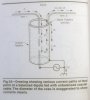
Fig 24 shows a coaxial cable feeding a hypothetical balanced dipole fed in the center. The coax has been drawn highly enlarged to show all currents involved. In this drawing the feedline drops at right angles down from the feed point and the antenna is assumed to be perfectly symmetrical. Because of this symmetry, one side of the antenna induces current on the feed line that is completely canceled by the current induced from the other side of the the antenna.

Currents I1 and I2 from the transmitter flow on the inside of the coax. I1 flows on the outer surface of the coax's inner conductor and I2 flows on the inner surface of the shield. Skin effect keeps I1 and I2 inside the transmission line confined to where they are within the line. The field outside the coax is zero, since I1 and I2 have equal amplitudes but are 180 degrees out of phase with respect to each other.

The currents flowing on the antenna itself are labeled I1 and I4, and both flow in the same direction at any instant in time for a resonant half-wave dipole. On Arm 1 of the dipole, I1 is shown going directly into the center conductor of the feed coax. However, the situation is different for the other side of this dipole. Once current I2 reaches the end of the coax, it splits into two components. One is I4, going directly into Arm 2 of the dipole. The other is I3 and this flows down the outer surface of the coax shield. Again, because of skin effect, I3 is separate and distinct from the current I2 on the inner surface. The antenna current in Arm 2 is this equal to the difference between I2 and I3.

The magnitude of I3 is proportional to the relative impedances in each current path beyond the split. The feedpoint impedance of the dipole by itself is somewhere between 40 to 75 Ohms, depending on the height above ground. The impedance seen looking into one half of the dipole is half, or 25 to 37.5 Ohms. The impenance seen looking down the outside surface of the coax's outer shield to ground is called the common-mode impedance, and I3 is aptly called the common-mode current. (The term common mode is more readily appreciated if parallel-conductor line is substituted for the coax cable used in the illustration. Current induced by radiation onto both conductors of a two-wire line is a common-mode current, since it flows in the same direction on both conductors, rather than in opposite directions as it does for transmission-line current. The outer braid for a coaxial cable shields the inner conductor from such an induced current, but the unwanted current on the outside braid is still called common-mode current.)

The common-mode impedance will vary with the length of the coaxial feed line, its diameter and the path length from the transmitter chassis to whatever is actually "RF ground." Note that the path from the transmitter chassis to ground may go through the station's grounding bus, the transmitter power cord, the house wiring and even the power-line service ground. In other words, the overall length of the ground can actually be quite a bit different from what you might expect by casual inspection.

The worst-case common-mode impedance occurs when the overall effective path length to ground is a multiple of 1/2 wave, making this path half-wave resonant. In effect, the line and ground-wire system acts like a sort of transmission line, transforming the short circuit to ground at its end to a low impedance at the dipole's feed point. This causes I3 to be a significant part of I2.

I3 not only causes an imbalance in the amount of current flowing in each arm of the otherwise symmetrical dipole, but it also radiates by itself. The radiation in Fig 24 due to I3 would be mainly vertically polarized, since the coax is drawn as being mainly vertical. However the polarization is a mixture of horizontal and vertical, depending on the orientation of the ground wiring from the transmitter chassis to the rest of the station's grounding system."

Page 26-20

"ELIMINATING COMMON-MODE CURRENTS-THE BALUN

In the preceding sections, the problems of directional pattern distortion and unpredictable SWR readings were traced to common-mode currents on transmission lines. Such common-mode currents arise from several types of asymmetry in the antenna-feed line system - either a mismatch between unbalanced feed line and a balanced antenna, or lack of symmetry in placement of the feedline. A device called a balun can be used to eliminate these common-mode currents.

The word balun is a contraction for the words balanced to unbalanced. Its primary function is to prevent common-mode currents, while making the transition from an unbalanced transmission line to a balanced load such as an antenna. Baluns come in a variety of forms..."
 

Attachments

  • Fig 24.jpg
    Fig 24.jpg
    588.2 KB · Views: 241
"...Such common-mode currents arise from several types of asymmetry in the antenna-feed line system - either a mismatch between unbalanced feed line and a balanced antenna, or lack of symmetry in placement of the feedline..."

Sooo...It looks as if I will need to keep the feedline 'symmetrical' from the feedpoint to the base of the mast.

I wonder how far I will have to go with that premise to keep CMC off of the line? After the line comes off of the roof, it will need to take a longer path back to my shack - compounding feedline losses...

Mole: do you use a short run of coax to your rig?
I'm glad you put that piece in here; it tells me one more thing to get right.
 
There's an entire section that I didn't feel like typing, but it goes on to talk about how common mode current will occur if you bring the feedline down slanted, but it's not really severe. It says that an interesting side effect is that when you do that, the dipole has about 0.2 dB more gain because it makes the null of the dipole on the side of the slanted line deeper, adding a little power to the front and rear lobes.

I'm guessing that pretty much everyone who installs a roof mounted tower probably has the coax laying on the roof at some point to get it into the shack. My run is about 100 feet total.

Don't make this more complicated than it needs to be. Get the wire in the air, run the coax or ladder line, if you want to use a choke or a balun with the coax then do it and talk :)
 

dxChat
Help Users
  • No one is chatting at the moment.
  • @ Wildcat27:
    Hello I have a old school 2950 receives great on all modes and transmits great on AM but no transmit on SSB. Does anyone have any idea?
  • @ ButtFuzz:
    Good evening from Sunny Salem! What’s shaking?
  • dxBot:
    63Sprint has left the room.
  • dxBot:
    kennyjames 0151 has left the room.