You may remember my homebrew 20/10 homebrew yagi that met its untimely end in an ice storm:
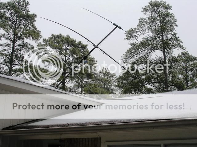
It was pretty clear that a push-up pole with a rotor and full size beam was not going to be a workable situation, despite the antenna weighing only 18 lbs. The cheap steel in one section of the mast apparently fatigued from the cold and it buckled like a toothpick.
In the months following I had given up on having a directional antenna for 20 meters , due to the following:
1. I cannot afford a tower and the associated heavy duty rotator, etc.
2. There’s not room for a phased vertical array.
3. I’m hemmed in by power lines on three sides and can’t safely put up a Bobtail, EDZ, etc., to favor the 45 degree azimuth I’m most interested in.
So I threw together a 20m ground plane and it did well for what it was, but if you’re used to a directional antenna it’s really hard to be without one, particularly on 20 meters.
Long story short, I decided a lightweight, monoband fixed yagi may just work. The wheels started turning, and I thought, “Why not make it a reversible beam?—Europe in one direction, New Zealand, part of Australia, and parts of Oceania in the other. Hmmmmm…”
So I did- I repaired the mast by sawing off the bent section and putting the remaining piece (now 4 feet shorter) back into the mast. The antenna itself went together like this:
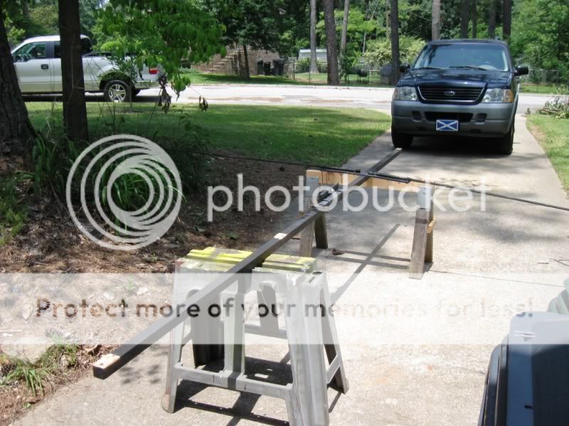
The wooden boom from the dualband that died in the storm was still usable, this is it with the 10 meter reflector still attached:
I decided to make the parasitic element a director with a switched-in stub making it a reflector, and leaving it in the reflector configuration normally—so a 10’ spacing was used to give a good direct match to 50 ohm coax (fed with a ferrite choke balun). The elements themselves are 18 gauge bare stranded wire, taped to fiberglass fishing poles as before—standard formulas were used for the initial length, expecting to have to tune them because of possible velocity factor introduced by being attached to the poles—turns out that was right.
The first step was to resonate the driven element to the frequency I wanted (14.175 MHz)
It was only 10’ off the ground (the length of the boom) but I had to start somewhere, and this was a lot easier than doing it on the roof.
With that done, the next step was to build the director and tune it 5% higher (ballpark figure) to 14.880 Mhz- testing shown here—same setup as the driven element: 10 feet off the ground with a temporary feedpoint connected to a MFJ-259:
With these so close to the ground I expected the tuning to change when it was hauled up on the roof (and I was right), but as I said, you have to start somewhere, and a couple of inches of wire had to be trimmed from both the driven element and the director to get them where they needed to be.
Now, the relay box and tuning stub were built:
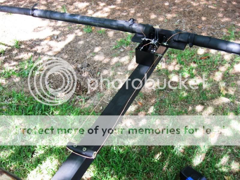
Honestly, I just added what I figured I’d need to make the reflector resonate 5% below the driven element, didn’t do any testing on the ground.
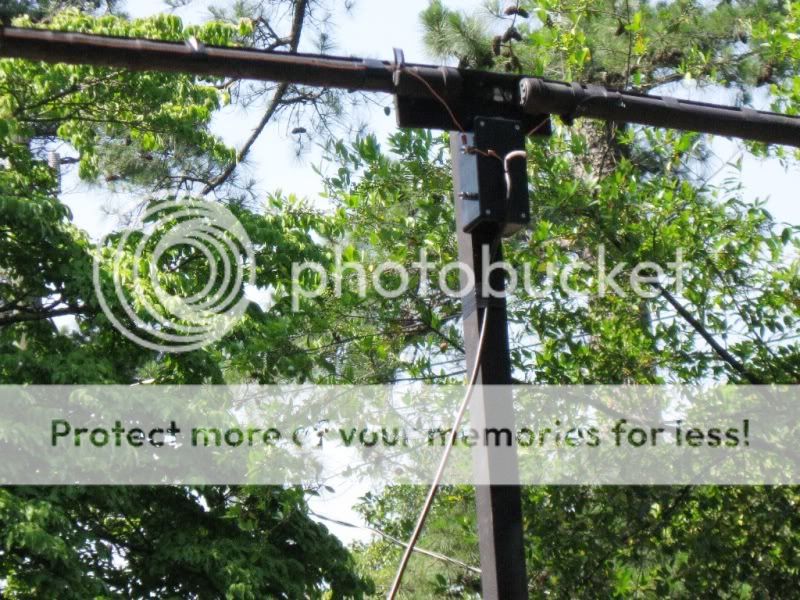
Details of the relay box:
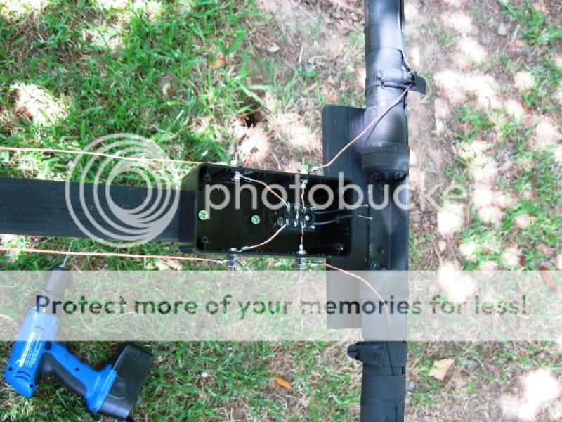
This isn’t complicated— since this is a parasitic element and the power across the relay contacts is much less than with a driven element, a plain old Radio Shack 12V DPDT relay was used. 10A contacts work just fine with the output of my SB-200. Since I’m more interested in the forward direction, the relay is wired with the NC contacts to the stub, while the NO contacts are shorted—So with no voltage applied to the relay that element is a reflector, and with 12V switched in the shorted contacts take that extra length out of the element making it a director. And there’s no reason it would have to be in the center if this were a wire beam hanging between trees or something—this is a wire beam supported by a non-conducting frame, anyway.
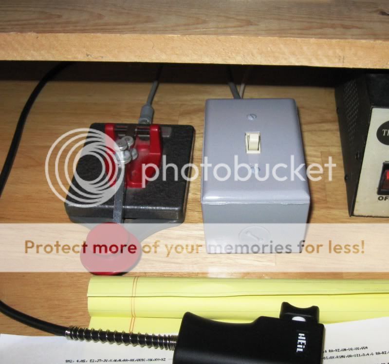
I used the rotor cable from the Alliant rotor to tie into the pigtails from the relay coil, and switch the 12VDC from shack with the highly specialized switch shown here:
Here’s the antenna in the air, boom height now only 33 feet:

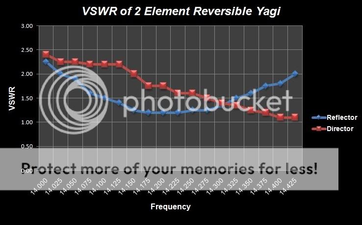
Now—since optimum element spacing is different for a 2 element yagi with a director as opposed to 2 elements using a reflector, the VSWR curves of the two are not the same (and most probably not the gain either), and I had to fiddle with the element lengths a bit once the antenna was up on the roof (where I could still reach it) to get a compromise bandwidth between the two. I’ll throw together a chart if anyone’s interested, but it’s still usable in both configurations across most of the band.
So, how does it work? Well, since I have had two other 2 element 20m yagis mounted in exactly the same place and still have the dipole in the same place for reference—it does what you’d expect it to do. Signals directly in the azimuth of the main lobe are generally 1 to 1 ½ S-units stronger than when the beam is reversed, and that’s what you’d expect to see. However, in some cases the difference is much more dramatic—a lot depends on what angle at which the signals arrive and how propagation may be changing, and who knows what that might be at any given moment.
But—even though 1 S-unit may not seem like much, it can make a huge difference on how well a signal can be copied in noise, and the QRM can sometimes totally disappear with the flick of a switch. This is not a big revelation to anyone who is used to directional antennas, but I say that to point out that even fairly inexpensive arrays can produce impressive results. In this case all I had to buy new was the relay/box and the switch/box, less than $20 total. Granted, the other materials were already paid for from other projects, but you get the idea.
My biggest challenge is having to go back out and put the beam back on azimuth after a big storm, but there haven't been too many of those.
Anyway, this is an idea worth pursuing if you have similar limitations to overcome. Is it a perfect solution to every possible situation? Nah, 'course not-- but nothing is.
The summer heat's nearly over-- get out there and build something!
73,
Rick
It was pretty clear that a push-up pole with a rotor and full size beam was not going to be a workable situation, despite the antenna weighing only 18 lbs. The cheap steel in one section of the mast apparently fatigued from the cold and it buckled like a toothpick.
In the months following I had given up on having a directional antenna for 20 meters , due to the following:
1. I cannot afford a tower and the associated heavy duty rotator, etc.
2. There’s not room for a phased vertical array.
3. I’m hemmed in by power lines on three sides and can’t safely put up a Bobtail, EDZ, etc., to favor the 45 degree azimuth I’m most interested in.
So I threw together a 20m ground plane and it did well for what it was, but if you’re used to a directional antenna it’s really hard to be without one, particularly on 20 meters.
Long story short, I decided a lightweight, monoband fixed yagi may just work. The wheels started turning, and I thought, “Why not make it a reversible beam?—Europe in one direction, New Zealand, part of Australia, and parts of Oceania in the other. Hmmmmm…”
So I did- I repaired the mast by sawing off the bent section and putting the remaining piece (now 4 feet shorter) back into the mast. The antenna itself went together like this:
The wooden boom from the dualband that died in the storm was still usable, this is it with the 10 meter reflector still attached:
I decided to make the parasitic element a director with a switched-in stub making it a reflector, and leaving it in the reflector configuration normally—so a 10’ spacing was used to give a good direct match to 50 ohm coax (fed with a ferrite choke balun). The elements themselves are 18 gauge bare stranded wire, taped to fiberglass fishing poles as before—standard formulas were used for the initial length, expecting to have to tune them because of possible velocity factor introduced by being attached to the poles—turns out that was right.
The first step was to resonate the driven element to the frequency I wanted (14.175 MHz)
It was only 10’ off the ground (the length of the boom) but I had to start somewhere, and this was a lot easier than doing it on the roof.
With that done, the next step was to build the director and tune it 5% higher (ballpark figure) to 14.880 Mhz- testing shown here—same setup as the driven element: 10 feet off the ground with a temporary feedpoint connected to a MFJ-259:
With these so close to the ground I expected the tuning to change when it was hauled up on the roof (and I was right), but as I said, you have to start somewhere, and a couple of inches of wire had to be trimmed from both the driven element and the director to get them where they needed to be.
Now, the relay box and tuning stub were built:
Honestly, I just added what I figured I’d need to make the reflector resonate 5% below the driven element, didn’t do any testing on the ground.
Details of the relay box:
This isn’t complicated— since this is a parasitic element and the power across the relay contacts is much less than with a driven element, a plain old Radio Shack 12V DPDT relay was used. 10A contacts work just fine with the output of my SB-200. Since I’m more interested in the forward direction, the relay is wired with the NC contacts to the stub, while the NO contacts are shorted—So with no voltage applied to the relay that element is a reflector, and with 12V switched in the shorted contacts take that extra length out of the element making it a director. And there’s no reason it would have to be in the center if this were a wire beam hanging between trees or something—this is a wire beam supported by a non-conducting frame, anyway.
I used the rotor cable from the Alliant rotor to tie into the pigtails from the relay coil, and switch the 12VDC from shack with the highly specialized switch shown here:
Here’s the antenna in the air, boom height now only 33 feet:
Now—since optimum element spacing is different for a 2 element yagi with a director as opposed to 2 elements using a reflector, the VSWR curves of the two are not the same (and most probably not the gain either), and I had to fiddle with the element lengths a bit once the antenna was up on the roof (where I could still reach it) to get a compromise bandwidth between the two. I’ll throw together a chart if anyone’s interested, but it’s still usable in both configurations across most of the band.
So, how does it work? Well, since I have had two other 2 element 20m yagis mounted in exactly the same place and still have the dipole in the same place for reference—it does what you’d expect it to do. Signals directly in the azimuth of the main lobe are generally 1 to 1 ½ S-units stronger than when the beam is reversed, and that’s what you’d expect to see. However, in some cases the difference is much more dramatic—a lot depends on what angle at which the signals arrive and how propagation may be changing, and who knows what that might be at any given moment.
But—even though 1 S-unit may not seem like much, it can make a huge difference on how well a signal can be copied in noise, and the QRM can sometimes totally disappear with the flick of a switch. This is not a big revelation to anyone who is used to directional antennas, but I say that to point out that even fairly inexpensive arrays can produce impressive results. In this case all I had to buy new was the relay/box and the switch/box, less than $20 total. Granted, the other materials were already paid for from other projects, but you get the idea.
My biggest challenge is having to go back out and put the beam back on azimuth after a big storm, but there haven't been too many of those.
Anyway, this is an idea worth pursuing if you have similar limitations to overcome. Is it a perfect solution to every possible situation? Nah, 'course not-- but nothing is.
The summer heat's nearly over-- get out there and build something!
73,
Rick