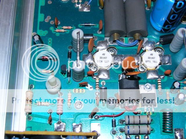
I used the AB/C switchable board bob85 designed and find it very stable even though I haven't tried tracking the heat off the pass transistor, I use the transistors base emitter junction method also mounted directly next to my finals and find that adequate but I'm not opposed to moving one of those to the pass transistor.

You are using an out of date browser. It may not display this or other websites correctly.
You should upgrade or use an alternative browser.
You should upgrade or use an alternative browser.
-
You can now help support WorldwideDX when you shop on Amazon at no additional cost to you! Simply follow this Shop on Amazon link first and a portion of any purchase is sent to WorldwideDX to help with site costs.
Bias design, amplifier design, filtering etc.
- Thread starter -=PEAKABOO=-
- Start date
peakaboo i would like to see the schematic but no worries if you cant find it, im pretty sure i dont have drawings either, sometimes i do a drawing when i am trying to help somebody else,
i must have drawn one for the bias boards to have the pcb made but i dont know where it is now:sad:
i must have drawn one for the bias boards to have the pcb made but i dont know where it is now:sad:
mack you have no need to track the pass transistor with that circuit,
the circuit itself is a low voltage low source impedance regulated power supply, it regulates any changes in ( vcc to the bias circuit, pass transistor conduction due to thermal effects, load drawn by the finals, )
the one sensing transistor does a decent job of tracking the finals,
its not perfect but its more than acceptable for any conventional bipolar hf /vhf/uhf amplifier,
the double tracking seems to improve the stability of simple regulator fed pass transistor setups as found in the majority of hf radios using bipolar output devices and the lower priced all band bipolar hf amplifiers,
if manufacturers gave us an extra terminal for a matched on die sensing diode we could really get a grip on amplifier operating point. __________________
mack you have no need to track the pass transistor with that circuit,
the circuit itself is a low voltage low source impedance regulated power supply, it regulates any changes in ( vcc to the bias circuit, pass transistor conduction due to thermal effects, load drawn by the finals, )
the one sensing transistor does a decent job of tracking the finals,
its not perfect but its more than acceptable for any conventional bipolar hf /vhf/uhf amplifier,
the double tracking seems to improve the stability of simple regulator fed pass transistor setups as found in the majority of hf radios using bipolar output devices and the lower priced all band bipolar hf amplifiers,
if manufacturers gave us an extra terminal for a matched on die sensing diode we could really get a grip on amplifier operating point. __________________
")
peakaboo i would like to see the schematic but no worries if you cant find it, im pretty sure i dont have drawings either, sometimes i do a drawing when i am trying to help somebody else,
i must have drawn one for the bias boards to have the pcb made but i dont know where it is now:sad:
I know I have a hand drawn schematic of the circuit I used. I will look for it. If you find your drawing or if someone else has it that would be cool. Just PM me.
Keep the talk going here guys, anyone that does not like it can choose not to click on this thread.
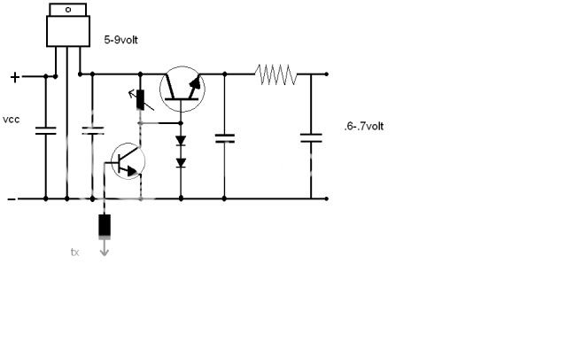
ken, heres the circuit my bias board is based on with some theory of operation,
i raised current limit using 4 parallel 1% metal film resistors to give me finer control over current limit,
a suitable dropping resistor was chosen to ease the pass transistors job,
extra lc filtering and decoupling was added in an effort to improve rf immunity,
the circuit seems to work well having very good voltage and load regulation plus decent thermal tracking,
http://www.communication-concepts.com/appnotes/AN758300Sharp.pdf
and a simple workable regulated circuit with thermal tracking as found in many hf radios amplifiers and the better cb amps
ken, heres the circuit my bias board is based on with some theory of operation,
i raised current limit using 4 parallel 1% metal film resistors to give me finer control over current limit,
a suitable dropping resistor was chosen to ease the pass transistors job,
extra lc filtering and decoupling was added in an effort to improve rf immunity,
the circuit seems to work well having very good voltage and load regulation plus decent thermal tracking,
http://www.communication-concepts.com/appnotes/AN758300Sharp.pdf
and a simple workable regulated circuit with thermal tracking as found in many hf radios amplifiers and the better cb amps
bob85, before I comment on the series regulator shown, can you post up a schematic or picture of the transistor circuit this is driving so I can get a better feel on how its loaded?
The series voltage regulator circuit used as a keying/bias circuit looks interesting but there may be some room for minor improvement once I know how its loaded.
Do any of you guys use PSPICE to simulate your designs after you design them?
Ken
ken,
that type circuit is typically loaded by the base emitter junctions of two transistors each with a base emitter resistor usually 10-15ohms they often have a diode to ground on the output as seen to the left of the input transformer,
it works with or without the regulator or tracking, adding the regulator stiffens load regulation a little but its not load stable,
hf sets use the regulator and tracking where most cb amps dont.
i have not used spice, i experiment and take measurements, could spice help choose more suitable components?
Last edited:
bob, is the amplifier emitter resistor AC bypassed and is their a base resistor too? I'm guessing the Amp is being baised "B" or "AB".
I would probably add a large value load resistor in parallel with the emitter - capacitor - resistor juntion. This will stabilize the transistor and bleed off capacitor charge when turned off.
PSPICE is a pretty good tool for simulating circuits as long as the models are accurately specified/built.
If you get a chance to post some part values, that would help too.
ken,
here are no emitter resistors in the amplifiers i have seen that use this type of biasing just 2x 10-15ohm typically from base to the grounded emitters, no ac bypassing,
at dc you have a 5-7.5ohm resistive load in parallel with whatever the transistor bases ammount to when they are forward biased at your desired operating point plus the clamping diodes forward conduction,
yes that type circuit is usually seen in class ab linear amplifiers,
do you mean try adding an extra load resistor in parallel with the pass transistor emitter cap?,
i dont have specific part numbers ken, the same basic circuit comes with a variety of components across a wide range of equipment,
it seems that many high wattage npn transistor with reasonable hfe will make a pass transistor and either diodes 4001's etc or the base emitter junction of a transistor will track temperature, a 1k variable works ok with a 5v or 9v regulator,
the base of the switching transistor is forward biased in receive and grounded in tx, one of several ways to turn bias on,
large cap on the pass transistor emitter followed by a choke, 47uf either side of regulator all bypassed with small polycaps
im sure there will be components ( diodes/transistors ) that work together better than others in a particular application
There has been many times that I wanted to bring a thread like this up but never did because I knew when I posted it that peoples mouths would watering with the thought that they might get to learn the right way to make an amplifier for a modulated signal.
ken,
here are no emitter resistors in the amplifiers i have seen that use this type of biasing just 2x 10-15ohm typically from base to the grounded emitters, no ac bypassing,
at dc you have a 5-7.5ohm resistive load in parallel with whatever the transistor bases ammount to when they are forward biased at your desired operating point plus the clamping diodes forward conduction,
yes that type circuit is usually seen in class ab linear amplifiers,
do you mean try adding an extra load resistor in parallel with the pass transistor emitter cap?,
i dont have specific part numbers ken, the same basic circuit comes with a variety of components across a wide range of equipment,
it seems that many high wattage npn transistor with reasonable hfe will make a pass transistor and either diodes 4001's etc or the base emitter junction of a transistor will track temperature, a 1k variable works ok with a 5v or 9v regulator,
the base of the switching transistor is forward biased in receive and grounded in tx, one of several ways to turn bias on,
large cap on the pass transistor emitter followed by a choke, 47uf either side of regulator all bypassed with small polycaps
im sure there will be components ( diodes/transistors ) that work together better than others in a particular application
I guess I misread your other post about the transistor amplifier configuration. If a small resistor was added to the emitter and ground, and was bypassed with a high capacity, high current poly type of capacitor, the transistor would have some built in thermal stability due to this negative feedback.
http://www.americancapacitor.com/PDF/VData.pdf
Yes, I am suggesting a load resistor be added to the regulator, pi filter junction to help with switching/keying time constants. I'm assuming the pi filter is to keep RF out of your supply, so make the resistor value equal to the filters insertion impedance for proper loading.
There has been many times that I wanted to bring a thread like this up but never did because I knew when I posted it that peoples mouths would watering with the thought that they might get to learn the right way to make an amplifier for a modulated signal.
So post up...