
You are using an out of date browser. It may not display this or other websites correctly.
You should upgrade or use an alternative browser.
You should upgrade or use an alternative browser.
-
You can now help support WorldwideDX when you shop on Amazon at no additional cost to you! Simply follow this Shop on Amazon link first and a portion of any purchase is sent to WorldwideDX to help with site costs.
Coil Loaded Dipole build - photo diary
- Thread starter Moleculo
- Start date
Hello Doc: How have you ben doing?
Doc said:
I'm afraid not. That coil is a loading coil for 80 meters, has nothing to do with the 40 meter antenna which is located below the 80 meter antenna.
The 80 and 40 meter antenna is one wire, with the loading coils are for 80 meters. Thats why I believe the 40 meter antenna has a wider bandwidth than the others. And I looked over the coils and did not see any capacitor so the coils are loaded coils not traps.
The antenna has three wires, the 80 / 40 meter wire, the 20 meter wire and the 10 meter wire. Mole has a pictire there showing the three wires and loading coil arrangement.
Intreresting to note that a lot of the dipole antennas are not supplied with Baluns. A older gentelmen in Mojave asked us locals for help on a dipole antenna for the ham bands. We installed a Balun and tuned the antenna for 80 and 40 meters and it significantly increased the antennas performance.
Jay,
If that coil is in the 80 and 40 meter dipole, then it isn't a simple coil, it's a trap. If it's a trap then it has not only a coil, but a capacitor, making it a tuned circuit. That tuned circuit is tuned for somewhere in the 80 meter band (bottom end) and presents a very high impedance to a 40 meter signal, thereby acting as on open switch cutting the wire off at that point. Just like any other 'trapped' antenna.
There are a couple of things that lead me to believe that that coil is just that, a coil, or loading coil. From what Mole' says, there's not much wire on the outer end of it, so it's not 'enough' length for 80 meters, so that coil is providing the needed inductance to make up for a shortened antenna. Another thing is that there is no apparent capacitor associated with it, so it isn't gonna act like a trap.
I think you might wanna re-think the thing about which/what the other 'elements' in that antenna are for. Keep in mind that 'even' multiples of harmonically related lengths are 'bad', but 'odd' multiples are 'good'. (For example, an 80 meter dipole is terrible on 40 meters, but works out well on 15 meters. "Works well" is relative, certainly doesn't mean is better than, or equal to a 15 meter antenna, just 'workable', sort of. Terrible way of putting it, ain't it?)
The 'Alpha-Delta' series of antennas work with harmonically related segment lengths. Some are shortened with loading coils. I honestly can't remember ever seeing one that used a trap (which doesn't mean a lot since I certainly haven't seen them all).
- 'Doc
(By the way, I'm doing as fine as possible considering the conditions. Which means that there are somethings much worse than they used to be, and something I can't tell any differences in. Not sure if my memory is in that first group or the second... Oh well, I'm having fun so who wants to worry about it, right? Went back to work, found I like it. Not the 'work' part, but the part about 'getting out of the @#$ house'! They even pay me!)
Oh, one last thing.
Baluns are great for their intended purpose, making the change between a balanced antenna and an un-balanced feed line, which can make a difference. They also have some very limiting characteristics, as in they are designed for use at particular frequencies. Get much away from those design frequencies and things go to 'pot' very quickly. I've found that for typical HF use, they just are not all that necessary, and are definitely NOT a 'cure-all'. Biggest difference is that using them or not using them affects the radiation pattern more than anything else. For antennas that depend on a particular radiation pattern, changing it ain't exactly the best idea in the world. For a typical dipole, they can certainly be done away with and not really be missed. As far as impedance transformation is concerned, they are misused to a very great extent. If you just 'gotta', then use a 1:1. Depending on a huge number of things, most people have no idea of what the actual impedances involved are (what they are supposed to be, sure, but the key words there are "supposed to be"). Oh well. If it works, good. If not, try something else...
Last edited:
Hello Doc: Good to hear your doing well. And you enjoy the work.
The Alpha Delta Antenna that I have has no capacitor in the coils, so I am thinking the manufacture made the coils to have enough inductive reactance to act as a choke to the 40 meter RF Energy, and a loading coil to the 80 meter RF Energy. Not being real happy with the antenna, I am looking at an antenna tuner feeding a balanced transmission line to a longer dipole for all the bands. The Barn is about 100 or so feet away from the house. So the Ladder (Balanced) Line will has minimum loss, and its cheap.
I just get a few more knobs to turn.
The Dipole, Quad, Yagi, and Loop antennas I have used and worked on have all showed improved performance when a Balun is installed between the Balanced antenna and the coax. No Balanced antennas have left here without a Balun. I have not tested dipole antennas from 160 to 10 meters to see how effective the Balun is. I would make a 160/80/40 meter dipole with a Balun with a few extra winds as I use with the higher HF Frequencies. The Balun costs so little vs its perfomance increase, in applying balanced current to the antenna and choking off unwanted RF Energy down the coax.
Jay in the Mojave
Baluns
Have to say I just don't like them. Probably more my fault than the balun's but they've just seemed to be another point of failure than useful for the antennas I use. They do work if used for their intended purpose, going from a balanced state to an unbalanced state. 'Nuff of that.
If you couldn't tell, I'm a fan of parallel feed lines, ladder line, whatever. I have a very nice tuner that will handle just about anything I've hooked to it, which is really saying something sometimes. The one in the HF radio ain't no slouch, but isn't as versatile as the big one. I've noticed that the amount of stuff I hear using ladder line typically increases from when using the same antenna with coax. Especially when using an antenna where it wasn't designed to be. The biggy with any type of parallel feed line is that it has much less loss and can withstand much more electrical 'abuse' than coax can. A high SWR can destroy coax, I haven't seen an SWR harm parallel feed line...yet. Got a 20:1 SWR? Who cares. You still have to stay sort of reasonable, but that 'sort of' has a much wider range...sort of.
Best advice for a multiband antenna using parallel feed line and a tuner is make it as long as possible. More/several wave lengths at the lowest frequency works very well @#$ near anywhere.
Then there's the qwerks, or down side of using parallel feed lines. Should be careful of what it's near, can't lay it on the ground or coil it up, it ain't 50 ohms. All of which can be 'got around', and is just different, not all that difficult. It typically doesn't like wet or snowy weather. (Open the window, whack it a few times with a broom stick, most of that goes away, sort of.)
Oh well, 'nuther who cares, just have fun with it!
- 'Doc
(Psst - just a lump of inductance ain't gonna make a 'trap'. Take another look at them wire segments.)
Hello Moleculo:
Look at your Alpha Delta Dipole Antenna Coils; is there a Capacitor inside the coil assembly? Making it a tuned trap? Or is it just a Coil. Again the Antenna Analyzer connected to the coil would tell you this by being resonate somewhere in the 40 meter band. But you would have to disconnect from the antenna. What I am thinking is that, is it possible for my Alpha Delta Antenna to not have the capacitors in the coils, as it was only 20 dollars at the TRW Swap Meet, causing me more grief that I deserve?
I bought a 500 Ft Roll of 12 gauge stranded insulated copper wire from Home Depot some time ago at a real reduced price. I don't think they understood just how low the price was, but us you can imagine they said the price was good to go. Ok then.......
I agree with Doc in using a long Dipole Antenna that is feed with open type Ladder line, or Balance Transmission Line, being feed by an Antenna Tuner. But I don't got no Antenna Tuner that will take legal limit and tune insane SWR ratios. So maybe I need to build one with all the other work I need to do. Or even buy one.
Yeah its raining here to in the Mojave Desert, kind of puts the kibosh on antenna work. But I think it would be ok for you to measure those coils. (humor)
Jay in the Great Mojave Desert, ....just down the road ah ways from the fillin station
Hello Moleculo:
Look at your Alpha Delta Dipole Antenna Coils; is there a Capacitor inside the coil assembly? Making it a tuned trap? Or is it just a Coil.
It's just a coil, wound with insulated bus wire: 68 turns on 1 3/4" OD pvc
Hello Tim :
Let me offer something to consider for your project.
If by chance you have a copy of ARRL Handbook 2000 I would direct
you to Chapter 20, page 20-13 and read the W8NX coaxial-cable traps.
Better yet Google W8NX Coaxial Cable Traps for a antenna I believe would
be just the right fit.
Total length 83.6.... A few extra dollars for some coax, But when only the Best will do")
Let me know what you think..
Best Regards,
John
Let me offer something to consider for your project.
If by chance you have a copy of ARRL Handbook 2000 I would direct
you to Chapter 20, page 20-13 and read the W8NX coaxial-cable traps.
Better yet Google W8NX Coaxial Cable Traps for a antenna I believe would
be just the right fit.
Total length 83.6.... A few extra dollars for some coax, But when only the Best will do
Let me know what you think..
Best Regards,
John
Hello Mole:
Ok we are back at square one, it appears that the coils in theses Alpha Delta Antennas are loading coils and not Traps (Traps = using a coil and a capacitor to make a band trap LC type circuit)
Again back to the discussion of the broad band 40 meter antenna having a wider bandwidth due to having loading coils (not a trap) at the end of its dipole antenna, causing a wider bandwidth.
If I had the time I would build a few antennas to prove this or disprove this out I would .....
It would be interesting to find out if the coil or the coils and added wire for the 80 meter band causes the wider bandwidth.
So Mole were are you with your dipole project?
Jay in the Mojave
It's just a coil, wound with insulated bus wire: 68 turns on 1 3/4" OD pvc
Are the coils using distributed capacitance of the turns to resonate the coils and thus are indeed traps? My tribander uses the sleeve casings covering the coils as capacitors to resonate the traps. Could be a similar idea with the Alpha Delta.
I was wondering about that, too. Can't have a coil without at least a small amount of capacitance.
The coils are just "plain old" coils. The wire used on both the Alpha Delta and mine is just solid wire. Theirs is insulated with a clear, thin film of some kind, mind just happens to have a little thicker jacket. I didn't build a coax coil trap because I was trying to copy what Alpha Delta did (and learn something).
Here's a quote from the link I attached earlier:
"It should also be noted that due to the high number of turns on each coil a trap like effect takes place. The inner A sections also work as a half wave dipole, for me that was a bonus as I gained a SWL antenna for the 25 - 27m bands (11 - 12MHz). You could experiment with different lengths for A and B to gain dual band operation or even tri-band operation on the 3rd Harmonic but that's up to you"
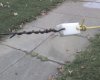
I took yesterday off from work and had a couple of hours to play with the antenna. I went over to my Dad's house since he has a nice big American Elm tree in the front yard to hang this from.
This is where I demonstrate how to screw up even the simplest projects. Remember the lengths that I measured and cut earlier for the 40m segment? Well I failed to plan for enough wire to run through the PVC and turn back on itself and then attach to the coil. So when I put the antenna up in the tree with wire attached to the PVC (but not connected to the coil) I now found that my dipole was resonant at 10mhz, instead of 7mhz. I had shortened the antenna because I didn't leave enough wire for the attachment. :headbang . Now I know how Homer Simpson feels.
Well, I wasn't going to let that stop me since I already had the thing in the tree, so I decided to experiment by putting the coil in play. Using the MFJ analyzer, I found that the coil did not change the resonant point significantly around 10mhz. Attaching the tag ends past the coil didn't affect the higher band, either. The higher band simply didn't "see" past the coil.
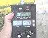
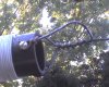
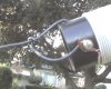
Unfortunatley I forgot my good camera, so all I had was my crappy cell phone camera. I adjusted the tag ends slightly to 65" each to get it in good shape on the lower side of 80m and called it good: I attached a fuzzy pic of the Analyzer showing how well it tuned up with a 1:1 current balun attached to the analyzer. as well as how the wire is attached to the coil on either side, as well as the tag end. I ran the ladder line into my jeep, used a small travel tuner to test out how difficult it would be to load up the higher bands. It was very, very easy to tune up 40m, 20m, & 10m. (Those were the only ones I tried). It was approaching time for the daily local MARS traffic net, so I retuned for the appropriate 75m frequency and successfully checked in using about 100 watts.
I intend to add some more length to the main wire to try and get it resonant on 7mhz. I would like to get it back up in the air and take some decent pics of the analyzer showing it with the coil attached and without at that frequency so you can see how little difference there is. I'll call the project successful, even though I screwed up the main length since the antenna really is useful and works fine anyway. I'm not sure how much I'll gain by having the antenna self resonant on 40m, except that it would be nice to be able to use it without the tuner.
Here's a quote from the link I attached earlier:
"It should also be noted that due to the high number of turns on each coil a trap like effect takes place. The inner A sections also work as a half wave dipole, for me that was a bonus as I gained a SWL antenna for the 25 - 27m bands (11 - 12MHz). You could experiment with different lengths for A and B to gain dual band operation or even tri-band operation on the 3rd Harmonic but that's up to you"
I took yesterday off from work and had a couple of hours to play with the antenna. I went over to my Dad's house since he has a nice big American Elm tree in the front yard to hang this from.
This is where I demonstrate how to screw up even the simplest projects. Remember the lengths that I measured and cut earlier for the 40m segment? Well I failed to plan for enough wire to run through the PVC and turn back on itself and then attach to the coil. So when I put the antenna up in the tree with wire attached to the PVC (but not connected to the coil) I now found that my dipole was resonant at 10mhz, instead of 7mhz. I had shortened the antenna because I didn't leave enough wire for the attachment. :headbang . Now I know how Homer Simpson feels.
Well, I wasn't going to let that stop me since I already had the thing in the tree, so I decided to experiment by putting the coil in play. Using the MFJ analyzer, I found that the coil did not change the resonant point significantly around 10mhz. Attaching the tag ends past the coil didn't affect the higher band, either. The higher band simply didn't "see" past the coil.
Unfortunatley I forgot my good camera, so all I had was my crappy cell phone camera. I adjusted the tag ends slightly to 65" each to get it in good shape on the lower side of 80m and called it good: I attached a fuzzy pic of the Analyzer showing how well it tuned up with a 1:1 current balun attached to the analyzer. as well as how the wire is attached to the coil on either side, as well as the tag end. I ran the ladder line into my jeep, used a small travel tuner to test out how difficult it would be to load up the higher bands. It was very, very easy to tune up 40m, 20m, & 10m. (Those were the only ones I tried). It was approaching time for the daily local MARS traffic net, so I retuned for the appropriate 75m frequency and successfully checked in using about 100 watts.
I intend to add some more length to the main wire to try and get it resonant on 7mhz. I would like to get it back up in the air and take some decent pics of the analyzer showing it with the coil attached and without at that frequency so you can see how little difference there is. I'll call the project successful, even though I screwed up the main length since the antenna really is useful and works fine anyway. I'm not sure how much I'll gain by having the antenna self resonant on 40m, except that it would be nice to be able to use it without the tuner.
Attachments
____________________________________________________________________________...Just for 'grins'. What's the third harmonic of that 80 meter frequency?? Don't expect 'exactness'.
- 'Doc
You wouldnt be thinkin it might be 20 meters now would Ya Doc
he he he....I have been looking at these on their web site, and looking back on moles comments
how this is constructed and conclude they are no more than a coil of wire sprayed
with a clear sealer. Is it that simple ? heck no, but then kinda sorta, maybe..
They call them Iso-Res Coils, Not Traps.
I was wondering about the extra length of wire past the coil ? and if playing with that
length would be worth some consideration, since the inductance to capacitance (L/C) ratio would seem to be high. I believe that wire is to help disapate the high voltages, and if so that would mean some added length but on the ends it would be a easy experiment..
With my short time and limited experience with wires, I have formed an opinion that
the second harmonic on these multiband wires seem to be the sweet spot.
Now I could be wrong about that and most probley I am wrong, However with that said It looks as if mole is gaining some ground here.
The best part so far is that no one has high jacked his thread and thats good, also its
very smart of them
Regards,
John___KD5WJY
dxChat
- No one is chatting at the moment.
-
@ Wildcat27:Hello I have a old school 2950 receives great on all modes and transmits great on AM but no transmit on SSB. Does anyone have any idea?
-
-
-
dxBot:63Sprint has left the room.
-
dxBot:kennyjames 0151 has left the room.