• You can now help support WorldwideDX when you shop on Amazon at no additional cost to you! Simply follow this Shop on Amazon link first and a portion of any purchase is sent to WorldwideDX to help with site costs.

End Fed 1/2 wave antenna

results

wgnganal.jpg

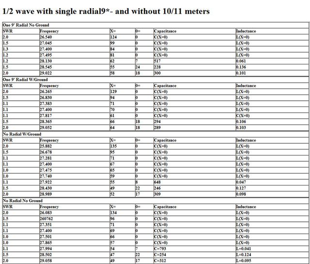
I gave you some numbers. If you can find anything useful in them . . .
Perhaps someone can tell me what to think of them.

With just a brief look before my eyes crossed, I don't think I see much difference. That is what I tried to say happened when I compared my A99 with my VA1 connected right at the feed point, with GPK, without GPK, with the mast in contact with the antenna, and without the mast in contact with the antenna as grounded or not.

I'll note again Homer, that I don't think I ever saw X=0, over such a range of frequencies like you consistently do, but the almost uncanny and consistent results you got are remarkable to me.

As I've said before, it seems like nothing I did to the A99, except raise it up, made any notable difference in the antennas match with maybe a little fluctuation in resonance that was maybe similar to what Homer reports.

I didn't see the feed line attached or not, make much if any difference to the match either, even though it was suggested I isolated without raising the antenna above the mast. I could see a bit of change in frequency when I changed the feed line length, but the match was not off the charts as I would expect...if I removed the counterpoise that we all feel is necessary for the proper function of any antenna.

Without knowing for sure and beyond question, I don't think the A99 significantly uses the mast/feed line for its counterpoise function that Kirchoff's rule addresses...regarding the two ports, in and out, showing the same magnitude...if tuned and installed correctly.

I don't want to crow too much yet, but I think Homer, I may have seen similar or close to what you see, at least in the lack of difference area. I wish I still had my Antenna Work Sheets that I threw away for all the work I did on my A99.

I wish I could explain more, but I still don't know but one thing, I didn't see much difference either with all of our iterations.
 
Last edited:
All those readings were done at 8' off the ground.
I can redo them at 23' up if you need me to. I still don't expect a difference.
 
All those readings were done at 8' off the ground.
I can redo them at 23' up if you need me to. I still don't expect a difference.

I don't need you to do it at 23' feet, I tend to agree.

Being close to the ground will add ground losses, so being close and then raising will likely change the resonance, and thus the matching values might change a bit, but I think what you are saying is the trend for the differences might remain about the same, right?

Something happened to your report again. Did you do that? It may be my funny computer. I still don't know what is going on here on WWDX or if it's my computer.

Here is just another indicator that might support my experience that nothing I do to my A99 makes much of a difference. I used your example for 1 radial as an example. Just compare the gain, angle, resistance, reactance, and SWR for these totally different models, and I think your might see the reason I claim radials on the end fed 1/2 wave just don't make much difference. Reason being, they are not near a current source.

I also added the currents log report, that shows the currents per segment for all the elements. I changed the segments for the radials and the mast to only one segment, just to get them to indicate their magnitude into one value. I also marked all of the wires. This report records the amperage per segment assigned to each element. These values might indicate to you some predictable results as you might imagine in comparisons from model to model. Also note the red lines on the Antenna View which represents current. It is obvious that the radials being there do have some decoupling effect, but is this enough to go to all the trouble of making changes to the antenna? I'm just not convinced.

View attachment Homer's .50 wave idea.pdf
 
Last edited:

Well Homer, I said I would ask you some questions after you posted your report. You really haven't described what you did at all, so there's lots of questions I could ask, but I can think of only one.

What does this mean, "1/2 wave with single radial 19*- and without 10/11 meters?"

Homer's .50 wave report..jpg
 
Last edited:
Yep Homer, I use to use a similar excuse when I was a kid in elementary school, and the teacher asked me, "Eddie, where is your homework?"

To which I promptly replied, "...the dog ate it."

After studying this report real close, I think the whole thing may have messed up. Those numbers are even closer than I thought possible.
 
Last edited:
No, the numbers are correct.
Perhaps the analyzer doesn't accept the popular point of view regarding feedline radial requirement for 1/2 wave end fed monopoles. I had no feedline whatsoever in line. Perhaps my analyzer was the radial, or maybe it ate my homework . . ?
 
There is a simple question regarding the readings I'd like someone to answer in simple terms without a lot of advanced mathematical squigglies, humpbacks, wingdings, and other gleanings from SETI and/or ancient Egyptian hieroglyphics.

"Why does the analyzer discontinue to measure capacitance and inductance when reactance equals zero? I realize the short answer is the measurements are out of range to the equipment, but what is occurring behind those frosted windows of secrecy?"
 
Last edited:
No, the numbers are correct.
Perhaps the analyzer doesn't accept the popular point of view regarding feedline radial requirement for 1/2 wave end fed monopoles. I had no feedline whatsoever in line. Perhaps my analyzer was the radial, or maybe it ate my homework . . ?

I agree Homer, you'll be accosted with the idea that your analyzer was just replacing the feed line, because the old claims have to prevail even without a real experience or real world testing in support. A few have tested radials and isolation on one of these antenna before, but as you and I tend to see, there just isn't much difference, so how accurate could these other reports be, if there just isn't much difference.

Thanks again Homer, for your effort to duplicate what I did. I am just amazed that again your work justified my findings and beliefs. Two out of two ain't bad for a start.

I just wish I could model my A99, and then compare some of the values you reported.
 
There is a simple question regarding the readings I'd like someone to answer in simple terms without a lot of advanced mathematical squigglies, humpbacks, wingdings, and other gleanings from SETI.

"Why does the analyzer discontinue to measure capacitance and inductance when reactance equals zero? I realize the short answer is the measure ants are out of range to the equipment, but what is occurring behind those frosted windows of secrecy?"

I didn't know what your concerns were, but I had a similar thought that the limited range for good results, caused your meter to default to "0". When my meter sees a value out of range, it produces a brief error message.

I can't tell you why however. I don't even know what the values for Capacitance and Inductance means in this regard.
 
I was just reporting everything on the MFJ screen.

I understand Homer. My meter probably does all of the stuff you reported, but each result is under a different function key on my meter, and each is produced by itself, so your meter is more versatile than the Autek VA1 in that regard.
 
Well Homer, it looks like nobody is interested in this subject...excepting maybe you and me. Even NB or BM haven't popped up appearing curious. I guess you're right this subject is best left in silence, because since you posted your results it's just me and you that have an interest in the truth we both have reported in our real world testing, right or wrong.

I do have another question about your test however.

I note that you didn't record the SWR. You may have don't it however, and the lowest and highest numbers for <2.00:1 SWR is the data points you noted, or so I assume.

I did the math and it indicates the bandwidth for the models with radials is a bit more narrow, than the models without radials. If I'm right in my assumptions here, do you realize this is also another thing that I've reported in regards to my work with my end fed 1/2 wave A99, with and without radials, for some time back?

It was my experience that was the only real thing I noticed when using radials vs. no radials on my A99. The bandwidth curve for the antenna with radials seemed a bit more narrow with more of a bowl shaped curve. The same antenna without the radials showed to be wider and flatter. For me, this alone might suggest that there was some improvement with the efficiency using radials, but that difference was was just too small of a change to really see...just working my radio.

I guess nobody believed me when I reported that either, because it might have shatter a few untested ideas that were claimed for the A99, with and without the GPK. So, I doubt anybody here has ever really checked it out either, excepting maybe you, when you did your testing and report.

So, I might even go so far as to now challenge others to do some testing, and report their findings as well. I know there are a few out there that can do the work, if their not too afraid it will force then to consider something else regarding a GPK, attached or not, to their A99.

My first clue to all this possible BS, that an A99 actually needs x feet of coax to work right, was revealed to me when I tested the match right at the feed point, and I saw no significant difference in the match compared to my using a 14' foot length jumper.
 
Well Homer, it looks like nobody is interested in this subject...excepting maybe you and me. Even NB or BM haven't popped up appearing curious. I guess you're right this subject is best left in silence, because since you posted your results it's just me and you that have an interest in the truth we both have reported in our real world testing, right or wrong.
I don't know much about how others feel, but I have noticed that some threads last longer than others. When I started this thread it was merely to share my effort to make and load effectively an end fed 1/2 wave no-radial antenna. Helping you test the effects of a GP on the antenna has been fun and interesting. I speculate that not many are as interested in the likes of the A99 more because they've decided it unworthy of mention in the same breath with more exotic antennas that have odd shapes. But in any case, it's okay with me because I get tired of a given antenna pretty quickly, too.
I do have another question about your test however.

I note that you didn't record the SWR. You may have don't it however, and the lowest and highest numbers for <2.00:1 SWR is the data points you noted, or so I assume.
Yes, the first column on the left is the SWR. I know some like to see the :1 behind the numbers, but my analyzer seems to think leaving it off is okay so I didn't write it down that way either. Anyone familiar with SWR will do as you've done and assume it is a report of the Standing Wave Ratio.
I did the math and it indicates the bandwidth for the models with radials is a bit more narrow, than the models without radials. If I'm right in my assumptions here, do you realize this is also another thing that I've reported in regards to my work with my end fed 1/2 wave A99, with and without radials, for some time back?
Me. too. I didn't do models, but I noticed that trend with the real world testing.
It was my experience that was the only real thing I noticed when using radials vs. no radials on my A99. The bandwidth curve for the antenna with radials seemed a bit more narrow with more of a bowl shaped curve. The same antenna without the radials showed to be wider and flatter. For me, this alone might suggest that there was some improvement with the efficiency using radials, but that difference was was just too small of a change to really see...just working my radio.

I guess nobody believed me when I reported that either, because it might have shatter a few untested ideas that were claimed for the A99, with and without the GPK. So, I doubt anybody here has ever really checked it out either, excepting maybe you, when you did your testing and report.

So, I might even go so far as to now challenge others to do some testing, and report their findings as well. I know there are a few out there that can do the work, if their not too afraid it will force then to consider something else regarding a GPK, attached or not, to their A99.

My first clue to all this possible BS, that an A99 actually needs x feet of coax to work right, was revealed to me when I tested the match right at the feed point, and I saw no significant difference in the match compared to my using a 14' foot length jumper.
I am not sure about what they are thinking, but I do notice many are enamored of the A99 Exposed thing and that seems to have settled the discussion for them. That's okay with me, too. I don't care about it. Personally, I've read that article a good half dozen times and gotten much of nothing from it except that someone cut the antenna open and took some less than totally revealing photos of it. I suppose that antenna expose's require a modicum of modesty to tantalize the taste buds of imagination.
Anyway, I'm glad to have helped you with whatever I could.
 
I don't know much about how others feel, but I have noticed that some threads last longer than others. When I started this thread it was merely to share my effort to make and load effectively an end fed 1/2 wave no-radial antenna. Helping you test the effects of a GP on the antenna has been fun and interesting. I speculate that not many are as interested in the likes of the A99 more because they've decided it unworthy of mention in the same breath with more exotic antennas that have odd shapes. But in any case, it's okay with me because I get tired of a given antenna pretty quickly, too.

Yes, the first column on the left is the SWR. I know some like to see the :1 behind the numbers, but my analyzer seems to think leaving it off is okay so I didn't write it down that way either. Anyone familiar with SWR will do as you've done and assume it is a report of the Standing Wave Ratio.

Me. too. I didn't do models, but I noticed that trend with the real world testing.

I am not sure about what they are thinking, but I do notice many are enamored of the A99 Exposed thing and that seems to have settled the discussion for them. That's okay with me, too. I don't care about it. Personally, I've read that article a good half dozen times and gotten much of nothing from it except that someone cut the antenna open and took some less than totally revealing photos of it. I suppose that antenna expose's require a modicum of modesty to tantalize the taste buds of imagination.
Anyway, I'm glad to have helped you with whatever I could.

Yep, you told us what your goal was in make this 1/2 wave end fed, and I appreciate your help. At the very least this will make a record that can argue some to the ideas that guys get from checking out what's on the local Truck Stop restroom walls.

I saved your report to my disk and it was very small type, so I printed it out and it chopped-off every thing before the Frequency column, and that is why I didn't see the SWR. You may see that where I reposted your report from my hard disk. It had nothing to do with your leaving off the :1 at the end of your SWR information.

If I said I got my bandwidth info from modeling, that was not what I meant to say. My idea for the bandwidth curve differences I've reported for a long time, testing between the A99 with and without radials, goes way back to my first real world testing of the antenna. I can model the A99, but not the matching device, so what I get is a terrible match. Thus I can't get anything constructive even running an SWR scan, so no SWR bandwidth curves in my models for this one. This is probably the big issue from my critics, as to why my models are worthless, because some show a bad match.

I say to them to just check out the models from their favorite guru's, and they won't likely find their antennas to be matched either. So make a real point.

I understand your last remarks too, and I also think that a lot of misunderstanding and miscommunications were leveled about that report. I have found it to be true with some A99's that I've had, and not true at all in most of the other cases.

So I knew the difference, and I posted my ideas on that subject, but no one listened. Again as I've tried to say before, I've found a few times that an A99's acted bad, and many times I could not tell, so IMO those problems are just bad workmanship, and has little to nothing to do with the design, whether the A99 uses the coax as a counterpoise or not.

I take it, you didn't notice such problems with your matching design, right?

Thanks for your help Homer. And you didn't even have a clue what you would find, but nobody else would have even bother.
 

dxChat
Help Users
  • No one is chatting at the moment.
  • @ Wildcat27:
    Hello I have a old school 2950 receives great on all modes and transmits great on AM but no transmit on SSB. Does anyone have any idea?
  • @ ButtFuzz:
    Good evening from Sunny Salem! What’s shaking?
  • dxBot:
    63Sprint has left the room.