
You are using an out of date browser. It may not display this or other websites correctly.
You should upgrade or use an alternative browser.
You should upgrade or use an alternative browser.
-
You can now help support WorldwideDX when you shop on Amazon at no additional cost to you! Simply follow this Shop on Amazon link first and a portion of any purchase is sent to WorldwideDX to help with site costs.
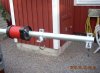
New antenna from Sirio Gain-Master
- Thread starter dxswe
- Start date
")
B
BOOTY MONSTER
Guest
thanks for the pics dxswe .
could you post some pics of the stub/wires running up the inside and an edge shot of the fiberglass tubes so we can see how thick the wall is .
do you have access to a imax 2000 for a direct comparison of tx and rx for your location and install ?
could you post some pics of the stub/wires running up the inside and an edge shot of the fiberglass tubes so we can see how thick the wall is .
do you have access to a imax 2000 for a direct comparison of tx and rx for your location and install ?
thanks for the pics dxswe .
could you post some pics of the stub/wires running up the inside and an edge shot of the fiberglass tubes so we can see how thick the wall is .
do you have access to a imax 2000 for a direct comparison of tx and rx for your location and install ?
More pics
I don't have Imax to compare with just now,but I had own an Imax for 3 years ago..
I'm gonna mounted this gm on saturday because I'm busy..
More reviews later..
Attachments
Last edited:
dxswe, does this bottom section come pre-assembled? I just curious.
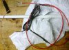
If you haven't already fully assembled the antenna, how about some pictures of the insides laid out beside the tubing, so we can see where the parts go in relationship to the four fiberglass tubes. If you've already assembled it, then how about a little description of how and where the parts ended up within the FG random. I would appreciate, if you can help me to understand the insides.
I suspect that the coax part is in the bottom half of the antenna and the wire part is in the top half and in the center is the capacitor where the coax and the wire connect, right? I also feel maybe the connector in the coax is a little above the top of the first section of fiberglass.
Keep us posted on how it performs and what you compare it with.
edit:
Thanks for the additional pictures, that helps. I was typing my post above while you posted the new images.
dxswe, does this bottom section come pre-assembled? I just curious.
If you haven't already fully assembled the antenna, how about some pictures of the insides laid out beside the tubing, so we can see where the parts go in relationship to the four fiberglass tubes. If you've already assembled it, then how about a little description of how and where the parts ended up within the FG random. I would appreciate, if you can help me to understand the insides.
I suspect that the coax part is in the bottom half of the antenna and the wire part is in the top half and in the center is the capacitor where the coax and the wire connect, right? I also feel maybe the connector in the coax is a little above the top of the first section of fiberglass.
Keep us posted on how it performs and what you compare it with.
edit:
Thanks for the additional pictures, that helps. I was typing my post above while you posted the new images.
Yes the bottom section is already pre-assembled from factory.
My antenna is already assembled and ready to take off:laugh:
Here is the manual for GM http://www.gain-master.it/Id-406 Gain master.pdf
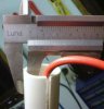
The first section is 29mm
second 24mm
third 19mm
topsection 15mm
Last edited:
Hi dxswe:
Thanks for posting those pics. Sure would like to hear some info on how this antenna is running at your station.
Did you get any local radio checks yet?
Please elaborate . . .
Thanks for posting those pics. Sure would like to hear some info on how this antenna is running at your station.
Did you get any local radio checks yet?
Please elaborate . . .
Yes the bottom section is already pre-assembled from factory.
My antenna is already assembled and ready to take off:laugh:
Here is the manual for GM http://www.gain-master.it/Id-406 Gain master.pdf
Good enough dxswe, I can see what I need from the nice pictures you posted. The wire portion of the radiator is obviously the upper half of the antenna and the capacitor is located in the center where the coax and the wire join together.
I'm sure the additional length of the G-M radiator and its effective matching scheme is likely to provide some performance advantages, but only testing could possibly tell if the difference is noticable.
For years, it has been my experience that if I could get my 1/2 wave antennas up close to the same tip height as my longer verticals with more gain, I would typically see similar performance. I consider comparing antennas at a similar current maximum a viable comparison. A lot of factors affect such comparisons, so others may get different results. I think a lot of antenna performance has to do with the magnitude of the CM currents that flow on the feed line, maybe for good and for bad.
I currently have one of my AstroPlane antennas up about 45' feet to the tip. Based only on my own opinion, I think the AstroPlane is a 1/2 wave center fed vertical radiator. According to the Avanti Patent it also produces a similar pattern on the horizon---as noted by Sirio's 5/8 wave Gain Master. IMO, I believe the AP design also handles CM currents nicely with its high impedance voltage node at the bottom hoop in the antenna minimizing such currents from flowing down the feed line. However, I can't really be sure.
The gauge I use for this consideration is based on the general idea that an antenna that is well decoupled from the feed line is often reported to be quieter operating---when conditions are said to be good and the noise level is low. I've heard claims for years how quiet the AstroPlane operates, so I figure it does a good job of minimizing CMC's and very often I can easily tell how quiet it is---when I work two antennas on a switch box.
Good luck and keep us posted on your G-M progress and performance.
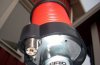
dxswe, there is something in the mounting bracket at the bottom of the G-M. It looks like a tube of some sort. Do you know what that is?

I think its a drainage holes..
dxswe, how much $ American did the antenna cost?
Perhaps 175$ US dollar..
I find a english webstore.. PJBOX UK: Online Store - ANT Sirio Gain Master
I think its a drainage holes..
Thanks dxswe. Whatever it is, it looks to be too small to be the end of the first FG tube section of the antenna. I thought maybe Sirio reinforced the bottom section for a couple of feet with a smaller tube inside the larger tube base to help support the antenna at the mount in that high stress area.
What is inside this image? Could this be two FG tubes telescoped and glued together?
.jpg")
I see drain holes in the coil former for the choke that should drain the radiator. The antenna looks to be very sturdy.
Damn, that antenna is going to be priced higher than I thought. I guess they're having to cover the cost of the Patent too.
Last edited:
Thanks dxswe. Whatever it is, it looks to be too small to be the end of the first FG tube section of the antenna. I thought maybe Sirio reinforced the bottom section far a couple of feet with a smaller tube inside the larger tube base to help support the antenna at the mount in that high stress area.
Could that be two FG tubes telescoped and glued together?
I see drain holes in the coil former for the choke that should drain the radiator. The antenna looks to be very sturdy.
Damn, that antenna is going to be priced higher than I thought. I guess they're having to cover the cost of the Patent too.
Perhaps it is possible to glue together sections .. But there is a slit in each section
so perhaps it is best to hose clamps ..
Perhaps it is possible to glue together sections .. But there is a slit in each section
so perhaps it is best to hose clamps ..
So as not to be confusing with my words, dxswe. I didn't mean to glue sections together, of course hose clamps are better.
I added an image to my post showing exactly where I'm pointing. It is the very end of the mount that I was looking at. It may be hard to see in the image.
dxChat
- No one is chatting at the moment.
-
@ Wildcat27:Hello I have a old school 2950 receives great on all modes and transmits great on AM but no transmit on SSB. Does anyone have any idea?
-
-
-
dxBot:63Sprint has left the room.
-
dxBot:kennyjames 0151 has left the room.