because you took your picture at about a 45 degree angle from the antnena itshard to tell if its laying horizontle or verticle. if its laying horizontle then your radiating more up then out. try it verticle like the driven el of a quad and i bet you will get better performance. bottom driven is horiz polarity and one side is verticle. id do horizontle for dx

You are using an out of date browser. It may not display this or other websites correctly.
You should upgrade or use an alternative browser.
You should upgrade or use an alternative browser.
-
You can now help support WorldwideDX when you shop on Amazon at no additional cost to you! Simply follow this Shop on Amazon link first and a portion of any purchase is sent to WorldwideDX to help with site costs.
Outdoor Loop
- Thread starter HomerBB
- Start date
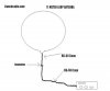
11 Meter Loop Antenna
Homer; is this how you did it?
Looks really easy to do.
How does the quietness of the receive compare to a vertical at the same height?
")
Homer; is this how you did it?
Looks really easy to do.
How does the quietness of the receive compare to a vertical at the same height?
Attachments
because you took your picture at about a 45 degree angle from the antnena itshard to tell if its laying horizontle or verticle. if its laying horizontle then your radiating more up then out. try it verticle like the driven el of a quad and i bet you will get better performance. bottom driven is horiz polarity and one side is verticle. id do horizontle for dx
You may be right. At the moment it seems to be responding as a horizontal would. Local verticals are way down, and DX is up. I would expect a straight up, ie vertical, radiation pattern to give me stronger local.
This antenna is an 11 meter center/spreader mounted version of what would be a Loop Skywire were it supported from the corners. Horizontal loops have horizontal polarity. I have had quad loops standing up on their edge, in fact, a quad beam fed from a side which did operate vertically just as you suggest.
How does the quietness of the receive compare to a vertical at the same height?
It is quieter than the vertical, but at the moment the only vertical I have up is the Sigma 4 at 41.5 feet. This is 30 feet.
You may be right. At the moment it seems to be responding as a horizontal would. Local verticals are way down, and DX is up. I would expect a straight up, ie vertical, radiation pattern to give me stronger local.
This antenna is an 11 meter center/spreader mounted version of what would be a Loop Skywire were it supported from the corners. Horizontal loops have horizontal polarity. I have had quad loops standing up on their edge, in fact, a quad beam fed from a side which did operate vertically just as you suggest.
Hey HomerBB, you know I have been getting ready to do a loop myself. Great job on yours! A lot of the ham loop sites I have seen recommend using the loop vertically for dx. I like the quietness of horizontal polarization. One nice thing about the new QTH is that the power lines are all buried, so QRM is not an issue here.
I know it's not a fair comparison, but my extended double zepp for 11 meters made it to WR080 in Hawaii the other day. And that was 12 feet in the air, under a roof.
I enjoy seeing all the stuff you build, so please keep up the great work and posts!
73,
RT307
You may be right. At the moment it seems to be responding as a horizontal would. Local verticals are way down, and DX is up. I would expect a straight up, ie vertical, radiation pattern to give me stronger local.
This antenna is an 11 meter center/spreader mounted version of what would be a Loop Skywire were it supported from the corners. Horizontal loops have horizontal polarity. I have had quad loops standing up on their edge, in fact, a quad beam fed from a side which did operate vertically just as you suggest.
thing is if you have it laying down like that then the 2 current nodes are a quarter wave out of phaze to the sides but standing upright its like 2 horiz el one above the other giving you a lower toa for horiz in the front and back directions
One might turn this loop vertical and place another loop ~10% larger in diameter and place it "X" distance behind the first loop, and come up with something similar to a PDL-II beam.
The second loop becomes the 'reflector'.
Then, one might add another loop ~10% smaller than the first loop and put it in front of the first loop and place "X" distance in front and have a three element quad beam.
The loop in front of the first loop now becomes the 'director'.
Actually, you would use the same spacing between these elements as you would a three element Yagi - to be correct ("X" distances).
Changing the position of the feedpoint of the first loop to either perpendicular or pointed to th the ground will change its polarization.
This may not be entirely accurate; but the idea is right.
Just playing with the possibilities here.
Maybe - that is what Homer is going to do next . . .
Last edited:
i love the antenna design very much !!!!!! beautiful job on making it .
can i get one from ya ?
from looking at it , its gonna work awsome .
Homer BB got down got down breakaaaaaaaaa.
i cant wait for the other projects you got up ya sleeve !!!!!! congradulations to ya !!!!
can i get one from ya ?
from looking at it , its gonna work awsome .
Homer BB got down got down breakaaaaaaaaa.
i cant wait for the other projects you got up ya sleeve !!!!!! congradulations to ya !!!!
Hey HomerBB, you know I have been getting ready to do a loop myself. Great job on yours! A lot of the ham loop sites I have seen recommend using the loop vertically for dx. I like the quietness of horizontal polarization. One nice thing about the new QTH is that the power lines are all buried, so QRM is not an issue here.
I know it's not a fair comparison, but my extended double zepp for 11 meters made it to WR080 in Hawaii the other day. And that was 12 feet in the air, under a roof.
I enjoy seeing all the stuff you build, so please keep up the great work and posts!
73,
RT307
Git 'er dun!
And don't worry about me, while I'm breathin' I'll be tinkerin'
thing is if you have it laying down like that then the 2 current nodes are a quarter wave out of phaze to the sides but standing upright its like 2 horiz el one above the other giving you a lower toa for horiz in the front and back directions
Now that's interesting. I'll have to think on this some more. I'll look around for this kind of info. You have any links?
With winter coming on it won't be much I can do outside, but you'll have to notice the ease with which this thing could be put on a boom.One might turn this loop vertical and place another loop ~10% larger in diameter and place it "X" distance behind the first loop, and come up with something similar to a PDL-II beam.
The second loop becomes the 'reflector'.
Then, one might add another loop ~10% smaller than the first loop and put it in front of the first loop and place "X" distance in front and have a three element quad beam.
The loop in front of the first loop now becomes the 'director'.
Actually, you would use the same spacing between these elements as you would a three element Yagi - to be correct ("X" distances).
Changing the position of the feedpoint of the first loop to either perpendicular or pointed to th the ground will change its polarization.
This may not be entirely accurate; but the idea is right.
Just playing with the possibilities here.
Maybe - that is what Homer is going to do next . . .
i love the antenna design very much !!!!!! beautiful job on making it .
can i get one from ya ?
Well sure you can. Here it is:
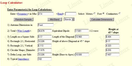
The dimensions are dictated by the length of the wire, which is viewable in the photo of the calculator I used to determine the wire length, spreaders, etc.
The parts in the above photos are:
two sets of 2" x 8-32 SS screws and nuts with washers.
3/4" soc PVC caps qty 3
3/4" tee all soc
2 feet long 1-1/2" PVC tube
3" x 1-1/2" adapter
6 inch length of 3" PVC tube
one stick of 10' x 3/4" PVC
2 sticks of 1/2" x 10' EMT (conduit)
prepared 6' piece of 75 Ohm coax
some tape to wrap around the EMT to take out slack between its diameter and the ID of the 3/4" PVC.
1. Take the 3 x 1.5 adapter and remove the stop inside the 1.5" end so the 1-1/2" PVC tube can go all the way through a couple inches. This is to make it sturdier than if the stop is in place. Glue the two pieces together as shown in the photos. I used self-drilling screws also for reinforcement.
2. Glue the 6" x 3" PVC tube into the adapter. I used self-drilling screws for reinforcement.
3. Drill two sets of holes into the 3" x 6" PVC tube at 90° to each other offset from each other.
4. Insert the two joints of EMT through the offset holes. Be sure they are inserted half way their lengths. This will form the characteristic cross shape of Quad spreaders. Secure them to each other in the center as you see done in the above photo. This provides stability and assures the spreaders remain in place.
5. Cut the 10' joint of 3/4" PVC into 4 equal parts - 2.5' each. Place caps on three of them, and the tee on the fourth.
6. Drill holes through the ends/caps of the three capped pieces of PVC so the wire can pass through them. Drill two holes, one in each end of the tee for the connector end of the loop as shown in the photos above.
7. Wrap sufficient amount of tape around the EMT spreaders to remove slack between the 3/4" x 2.5' sections when they are slipped onto the spreaders. Do this near the end of the EMT, and at 49" out from the outside edge of the 3" PVC center tube.
8. Slide the PVC sections onto the four EMT spreaders. Thread the pre- measured, pre-cut wire through the holes of the three caps securing the ends of the loop wire with the SS screws on the two sides/ends of the tee. Slide the four PVC sections out equally from the center until the wire is taut.
9. attach 6' piece of 75 Ohm coax. Tape or zip-tie this along the spreader . Done.
B
BOOTY MONSTER
Guest
very nice ! did you have any place for wire length adjustment ? or just use the 36 ft 8 1/8 inch recommended length ?
So far, just the recommended length. When i get the analyzer on it I may have to make adjustments. We'll see.
dxChat
- No one is chatting at the moment.
-
@ Wildcat27:Hello I have a old school 2950 receives great on all modes and transmits great on AM but no transmit on SSB. Does anyone have any idea?
-
-
-
dxBot:63Sprint has left the room.
-
dxBot:kennyjames 0151 has left the room.