• You can now help support WorldwideDX when you shop on Amazon at no additional cost to you! Simply follow this Shop on Amazon link first and a portion of any purchase is sent to WorldwideDX to help with site costs.

Outdoor Loop

Homer may be it is best to leave that loop right where it is.

It is definately a high angle of radiation antenna, but that is not really a bad thing as you have all ready found out "sometimes" it beats the vertical.

So with the loop and the vertical you have the best of both worlds, high angle and low angle for receive and transmit.
 
The Ultimate Guide to 11 Meter CB Antennas

Interesting read. Some great info on that page.

If I'm not mistaken, the horizontal loop's polar pattern is much like the picture below. However this is looking down upon a loop that is set up vertically; not horizontally. This would mean that the angle of radiation is nearly vertical. So I don't know how giving a turn would change anything. Care to answer that question?

I think the design used by Homer is a classic example of a "Near Vertical Incident Skywave" or "NVIS" type of antenna:

The NVIS Antenna
 

Attachments

  • dipolequadpat.jpg
    dipolequadpat.jpg
    19.1 KB · Views: 3
The Ultimate Guide to 11 Meter CB Antennas

Interesting read. Some great info on that page.

If I'm not mistaken, the horizontal loop's polar pattern is much like the picture below. However this is looking down upon a loop that is set up vertically; not horizontally. This would mean that the angle of radiation is nearly vertical. So I don't know how giving a turn would change anything. Care to answer that question?

I think the design used by Homer is a classic example of a "Near Vertical Incident Skywave" or "NVIS" type of antenna:

The NVIS Antenna

i think the polarization is still horizontle even though the pattern is high angle which makes it look like verticle but shouldnt be confused with verticle polarization. that pic is looking strait down so it still looks horizontle to me
 
There is one parameter that I don't think has been factored into this discussion of the radiation properties of this antenna in terms of it being an NVIS type.

Height above ground.

As I understand it, the optimum distance above earth, or a second loop/dipole of an effective NVIS system is between 0.1ƛ and 0.2ƛ, with optimum modeled at 0.175ƛ. that would make it above a reflector, earth or mechanical, set at from 3.6' to 7.2', optimum being only 6.3' for 11 meters.
Otherwise, the radiation pattern would not follow that of the classic NVIS antenna.

I am not arguing against how this loop is deployed, or its physical configuration having that of the Loop Skywire, which when set up as an NVIS behaves as discussed. I am saying the discussion is incomplete with respect to the way it's been suggested this antenna should be radiating until that point is covered.

What about this?

I certainly don't mind Show and Tell being resourcefully turned into Show and Learn.
 
The reason I brought the info up and asked the question is simply because I don't the answer myself.

But a few of us did bring up the height issue here.

Height is a determining factor for the NVIS.

Not meaning to steal the thread - as much as I am trying to bring clarity to it - is all.

Keep on building and posting - I'm enjoying it . . .
 
Quote BOOTYMONSTER:
if it can out do the v4k sometimes at the lower feed-point , imagine what it could do at the same tip height . it would require a few sets of guys though

Answer:
There will always be a large different between vertical and horizontal polarized antennas. To debate if one will do better at different heights is non constructive, unless one accurate models both and bares in mind the ground circumstances and gives a reference point of what is needed...
With this horizontal loop it is most likely not going to be an improvement, so Doc his thoughts are mine as well.

Quote HOMER BB:
It has done remarkably well on DX, but perhaps you are right, and as well as it is something better in the way of a loop may be more useful.

Answer:
Not to be irritating, but most antennas have done remarkably well on DX for the last couple of months. Going through your “worked” list I notice you have worked most of the time US.

If I do a log search for the last couple of months and go into DX for me.
I noticed for example there are about 30-40 MOBILE stations from the west coast here in my log in Holland (Europe). From Alaska down to Mexico. But also a mobile station from New Zealand via Long path.

That’s not to show how "good" I am, cause I’m not…it is to show how great propagation is over the last couple of months. And I’m quite confident most of them worked with “less” antenna compared to yours right now.

Another positive side of your antenna is that it is a horizontal antenna which is known for less “noise” compared to a vertical. However you will be better off using other “shapes” which I have provided already. There can be a slight advantage right there in comparisment to a “noisy” vertical. The same advantage can be seen from a beverage antenna on low bands compared to a vertical. Though the antenna (beverage) lacks gain…the noises are so much lower the signal still gets out on top.

And a horizontal antenna has more ground gain compared to a vertical.

I want to make clear that I have said: The radiation plot tends to be more straight up with the minor lobs under a "skip" angle.
That doesn’t mean there aren’t any…it is however not the “best" of this antenna. There are minor lobs under a skip angle. But the “best” function of this antenna is not that low angle but rather straight up.

@ NEEDELBENDER
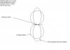
Yes, it seems you’re on the right track. If we take two of these loops and separate them 5/8 wavelength (approx) The lob straight up will be down and all the gain will be forced under a “dx” angle. If we take for example two one at 8 meters and the other at 14,5 meters the gain will be around 7 dBi (with ground gain!!) with a figure 8 pattern. And the take-off angle will be around 13 degrees.
Attached you will find a document containing those plots.


@ WAVERIDER:
GOOD THINKING! If one is a relative “small gun” and it is very wise to put up several smaller antennas that “cover” the different radiation angles. There can be up to several S-units difference in favor for an antenna which actually has less gain.

@ All the vertical/horizontal/nviss enthusiasts.
I’ll keep it a bit short, as it already turns into a long story...perhaps if it does raise some questions it might be wise to open a new thread.

The antenna is horizontal polarized. Polarization has to do with how the electromagnetic field behaviors (how it is “radiated” from the antenna.

What makes an antenna a NVISS "type"antenna ? Well, there is only one thing. It needs to radiate as much “power” straight up. (This is bad for real dx of course).
How can we accomplish this?
Oke, now we have two things.
First we have to get rid of the idea the antenna its pattern is made up "only"from the antenna. The antenna its pattern is made up from the antenna, near the antenna and far beyond the antenna. Ground has a major influence.

Most low placed antennas have a high radiation angle…but by far not all.
Just imagine your average vertical, it has a relative low angle when placed at ground level.
Oke, to state…only a low height will provide NVISS is inaccurate.
If it concerns a half wave horizontal dipole, yes …it is very true.
But NVISS can also be made due to the “shape” of the antenna.
How is the pattern made up? Well perhaps something for another thread as well.
Thankfully with the great help of modeling software one can model most situations by using free programs like 4NEC2 (my favorite fee software) but also others like MMana, Enzec demo for some purposes. ...yes that might be something for the future...how is a pattern made up ?, how can we benefit of "terrain" etc etc.

Oke, BACK TO THE LOOP :
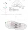
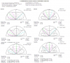
Attached you will find a document containing the horizontal loop at different heights and its take off angle to get an impression.
At the bottom you will find the stacked configuration.
Though the gain is already around 7dBi at 13 degrees (8 figure pattern). And the upwards lob isn’t an issue anymore..the gain lacks a big compared to a small 2el yagi.
A small 2el Yagi will have about 12 dBI (including ground gain of course) when placed at the average height of the stacked system.


Hope it helped..

Kind regards,

Henry HPSD,
19SD348
All about antennas
 

Attachments

  • stacked horizontal quad loops forum.PNG
    stacked horizontal quad loops forum.PNG
    121 KB · Views: 3
  • horizontal quad loop different heigths wwform.PNG
    horizontal quad loop different heigths wwform.PNG
    196.1 KB · Views: 7
  • Like
Reactions: 1 person
Thanks, Henry, for this information and superb responses to the points raised on the thread. If someone wishes to start another thread it's okay, but I am okay with any and all discussion of this subject at any level whatsoever right here.

Robb, You've done everyone a service by asking the right questions, and raising the right points.

I am a better learner hands on, and this particular idea has nagged the edges of my brain for some time. I posted to the forum hoping interest would cover the potential of the loop while I have my 3D model in the air.
I hear and read a lot, but my visual acuity is much better when I have materials in my hands.
 
The Ultimate Guide to 11 Meter CB Antennas

Interesting read. Some great info on that page.

If I'm not mistaken, the horizontal loop's polar pattern is much like the picture below. However this is looking down upon a loop that is set up vertically; not horizontally. This would mean that the angle of radiation is nearly vertical. So I don't know how giving a turn would change anything. Care to answer that question?

I think the design used by Homer is a classic example of a "Near Vertical Incident Skywave" or "NVIS" type of antenna:

The NVIS Antenna

if that pattern is even remotely similar to what your antenna is doing homer ...... putting it directly under or at your v4k's feed-point with a separate coax run to a switch box could be a option for different skip angles and polarization since each antenna picks up signals the other doesn't at different times/conditions .
 
The reason I brought the info up and asked the question is simply because I don't the answer myself.

But a few of us did bring up the height issue here.

Height is a determining factor for the NVIS... - I'm enjoying it . . .

actually, getting an NVIS antenna to perform well on the higher freqs (IE: 11 meters) is an uphill struggle.

they ARE freq dependent and usually are not used above 40 meters with any real success. even then, they are NOT a "DX" antenna.

their strong point is reliable communications covering (about) 600 - 800 miles distance.
 
  • Like
Reactions: 1 person
the 11 meter high pattern looks perfect for sporadic e dx.
henry, does that model consider ground in its gain calcs? i didnt see anywhere where it showed a ground height measurement so i was wondering if the 7.7dbi was before ground gain or after?
 
I did talk to Homer on .385/LSB when he was running his loop the other day. Seemed to work quite nice and gave him that report. Had him the red here in CA - BTW - which isn't the typical signal report given him before from his using the V4. He did a comparison with his attic loop and hiss external loop; the external loop seemed to work better, as it was higher up than the attic loop.
 
Hello Needle bender,

The angles straigth up produced by the antenna are not "handy" for sproadic e.
Though sproadic E requires a "higher" toa then the one we want for true DX, straight up is far beyond usefull.

The different heigths above ground are mentioned in each plot.
for example the first plot is "@5 meters heigth".
(roughly multiply that number by 3 to get feet.)

Kind regards,

Henry 19SD348
All about antennas
 
if that pattern is even remotely similar to what your antenna is doing homer ...... putting it directly under or at your v4k's feed-point with a separate coax run to a switch box could be a option for different skip angles and polarization since each antenna picks up signals the other doesn't at different times/conditions .

I would need some input on whether the vertical above the flat loop would have a negative impact on the performance of both. They are both resonant in the same band, so it begs the question of whether they would face seriously negative coupling issues per the TOA of the loop as discussed.
 
actually, getting an NVIS antenna to perform well on the higher freqs (IE: 11 meters) is an uphill struggle.

they ARE freq dependent and usually are not used above 40 meters with any real success. even then, they are NOT a "DX" antenna.

their strong point is reliable communications covering (about) 600 - 800 miles distance.

That's what my reading on the NVIS has said.

As a matter of information, my intent with the loop so made and mounted was not to develop and NVIS. That has arisen as a consequence of the nature of this antenna's radiation properties.

It's relevant info, however, to this discussion.
 

dxChat
Help Users
  • No one is chatting at the moment.
  • @ Wildcat27:
    Hello I have a old school 2950 receives great on all modes and transmits great on AM but no transmit on SSB. Does anyone have any idea?
  • @ ButtFuzz:
    Good evening from Sunny Salem! What’s shaking?
  • dxBot:
    63Sprint has left the room.
  • dxBot:
    kennyjames 0151 has left the room.