
First, the good! The 2000GTL is here and trouble free!It's been tuned(Nothing cut), two-switch channelling, unlocked Clarifier. Everything was well-done and easily recognizable Wired a Turner +3 to it and ran some SSB today. Did very well. Nothing to do and nothing will be done on this radio.
Now, the Bad! The Grant XL mobile I bought came yesterday afternoon. First problem, the guy had a six-position switch put in it for channels. Totally screwed up. I thought I had the channels figured out and tried a radio-check on channel 19. turns out I was on Channel 34. I don't think whoever did this even tried to set the frequencies at L59,L22 and L23. I'm going to remove all and do a two-switch channel job. The Clarifier is a mess, no kc up and almost 10 down. There are RV on the bottom I cannot figure out and he did things with the front switches that don't make sense. I took some photos, wait til you guys see ll the junk around the 8719 for the channels.
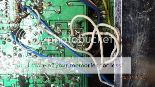
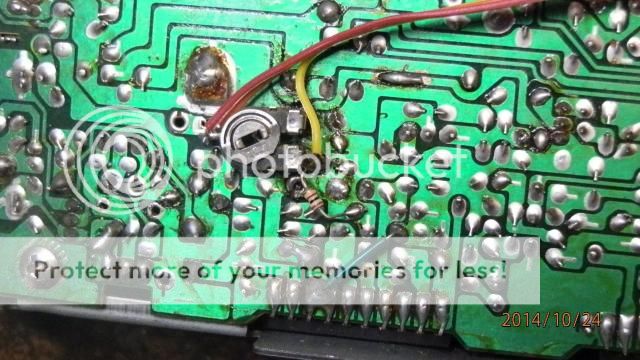
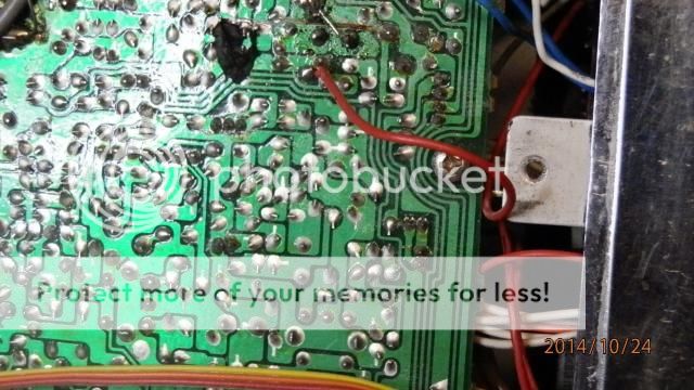
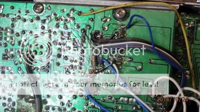
Look at all the crap.
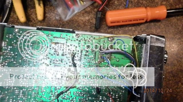
Here's my plan I'm gonna remove the six position switch, the wire, the resistor and the diodes and transister. Unhook the clarifier wiring, unhook whatever the bright/dim and Hi/Low wires, That VR that looks to be going to the AM power and try to start over. If you guys notice anything I need to be warned about I'd appreciate it. You all have been super helpful to date, you're a great bunch.
Now, the Bad! The Grant XL mobile I bought came yesterday afternoon. First problem, the guy had a six-position switch put in it for channels. Totally screwed up. I thought I had the channels figured out and tried a radio-check on channel 19. turns out I was on Channel 34. I don't think whoever did this even tried to set the frequencies at L59,L22 and L23. I'm going to remove all and do a two-switch channel job. The Clarifier is a mess, no kc up and almost 10 down. There are RV on the bottom I cannot figure out and he did things with the front switches that don't make sense. I took some photos, wait til you guys see ll the junk around the 8719 for the channels.


Look at all the crap.

Here's my plan I'm gonna remove the six position switch, the wire, the resistor and the diodes and transister. Unhook the clarifier wiring, unhook whatever the bright/dim and Hi/Low wires, That VR that looks to be going to the AM power and try to start over. If you guys notice anything I need to be warned about I'd appreciate it. You all have been super helpful to date, you're a great bunch.


