• You can now help support WorldwideDX when you shop on Amazon at no additional cost to you! Simply follow this Shop on Amazon link first and a portion of any purchase is sent to WorldwideDX to help with site costs.

There's a First Time For Everything

HomerBB

Sr. Member
Jan 4, 2009
3,933
2,633
273
68
Rogers, Ar
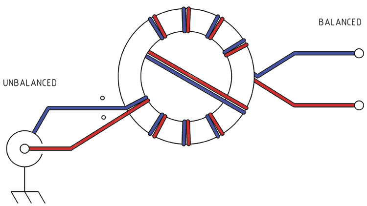
Those of you who have an oilfield background will be familiar with the term "worm". For those of you who are unfamiliar it translates to "newbie", "greenhorn", "plebe" or similar when your being nice (it can be fighting words, too). It's in the nice sense that I see myself as a worm where most things "Amateur" are concerned. There are rare occasions for which the CB antenna homebrewer finds a need to wrap a toroid balun seeing those are single band antennas. Things have changed. I decided now is as good a time as any to get started, and with three small (1-1/2" dia.) -61 toroids lying about I wanted to see if I could produce a 4:1 multiband balun. Believe it or not I did. With 200 Ohms on the load end of this thing I got under 2.1:1 SWR all the way from 160m to 6m, the worse being 1.9:1 at the upper edge of 6m.
It's little, and likely very QRP, but I feel pretty good about my first time to try this.
20170425_174428-01.jpeg
 

I decided to try to make a 1:1 choke balun with my 3rd ferrite. It works as I thought it would if I got it close to right. Beginning in 160m with a 50 Ohm load on it the analyzer read the SWR as 1.0:1. The readings remained in low to mid 1._:1 through 27Mhz. Through 10 meters the SWR started near 2:1 and remained under 3:1. In the 6m band it was between 4:1 and 5:1 SWR.
Now I want to try it on a windom. 6m will need its own antenna, I suppose...
20170427_193448-01.jpeg
 
Typically that design when crossing the wires to the other side of the toroid, you also cross the wires through the center of the toroid, like this:

f7yu7.gif


On a 1:1 balun it doesn't really matter that much, however, for some other designs that use this technique this omission may have some effects on how well the balun performs.

The first design you used above is known to have a very wide bandwidth, consistently covering the range of frequencies you mention. This second design should have an even wider bandwidth. One thing that can sometimes change where the SWR range falls with this design is actually the diameter of the wire and the thickness of the insulating material, so if you have trouble with this design in the future the first thing I recommend is trying a different type of wire. The biggest difference between these and the ones I have made in the past is I prefer to use thermaleze-coated magnet wire.

Essentially, what is happening with both of your balun designs is the two wires that are wrapped side by side are acting like balanced feed line around the toroid, and any unbalanced part of the signal is radiated into the toroid and effectively lost as heat. Essentially none of the balanced component of the signal is ever absorbed by the toroid, making these very efficient designs. I like these designs as they have the advantage of working irregardless of the toroid material, unlike some other designs that requires specific toroid materials for a specific frequency ranges.

Good job again.


The DB
 
  • Like
Reactions: HomerBB
Doublet and home brew balanced tuner....you'll be glad you did.;)

A balanced L or a link coupler like the K1JJ tuner.
 
Do you recommend I do them with coated magnet wire? I was using what was at hand, but can easily picj up some magnet wire tomorrow.
 
Doublet and home brew balanced tuner....you'll be glad you did.;)

A balanced L or a link coupler like the K1JJ tuner.

Don't forget the balanced feed line if possible... To many people these days get stuck on coax when their are times when the older balanced feed lines are superior when you have high SWR between the antenna and tuner.

Do you recommend I do them with coated magnet wire? I was using what was at hand, but can easily picj up some magnet wire tomorrow.

If it ain't broke don't fix it, but if you have problems, or want to try for more bandwidth it is a place to start.


The DB
 
  • Like
Reactions: HomerBB
Is this mechanical tuner, or baluns? I have a IC746 with built in tuner, and an MFJ external tuner. 939, I think.

I guess you would call them mechanical. The balanced L can be built with 2 roller inductors and a variable cap. I use copper tubing and heavy duty clip leads. It needs a 1:1 current balun at the input of the tuner.

The K1JJ is a coil 30 to 40 turns of 1/4 or 3/8 copper tubing with a link coil of about 5 turns wrapped around the center. No balun required. You tune it with variable cap and different clip locations.

Both are a pain to get figured out initially but worth it. An antenna analyzer and patience is a must. Later use an rf ammeter to measure current on the ladder line. Find the combination of taps that give the most current to the antenna with the same carrier.
 
  • Like
Reactions: HomerBB
Don't forget the balanced feed line if possible... To many people these days get stuck on coax when their are times when the older balanced feed lines are superior when you have high SWR between the antenna and tuner.


If it ain't broke don't fix it, but if you have problems, or want to try for more bandwidth it is a place to start.


The DB

Absolutely, I don't think coax would work too hot on the output of these tuners. I bought my ladder line at home depot. #8 thhn and some 4" electric fence spacers from tractor supply.
 
  • Like
Reactions: HomerBB
I made a ladder line once with home depot supplies. Used dowell with
0076_zpsbbcd3563.JPG
holes drilled through the ends for spacer. Only made about 10' of it. Took about 7 forevers measuring, cutting, drilling, weaving wire through the spacers, evenly spacing them along the wire, applying silicone to fix them in place, etc. I used it for an extended zepp antenna. Seemed to work, but right above the ridge of the house proved to be too noisey so I rarely used it.
 
  • Like
Reactions: 2RT307 and LeapFrog
I made a ladder line once with home depot supplies. Used dowell with holes drilled through the ends for spacer. Only made about 10' of it. Took about 7 forevers measuring, cutting, drilling, weaving wire through the spacers, evenly spacing them along the wire, applying silicone to fix them in place, etc. I used it for an extended zepp antenna. Seemed to work, but right above the ridge of the house proved to be too noisey so I rarely used it.

I get the big bags of cheap pens and take out the insides so I have just the tubes, then I cut the tubes into half or third lengths. I feed a thin zip tie through the cut tube, around the wire at the far side, and back through the tube. If your zip ties aren't long enough for that you can use one in each direction through the tube. That is the easiest and cheapest way I have yet found to make ladder line.


The DB
 
May need some advice on that tuner should (when) I get started on it.

The easiest designs that cover a wide range for manual matching networks is the T network...

t.jpg


The center of the input coax goes through two variable capacitors (the two Z1's in the image above) to the center of the coax output (or one of the balun inputs if you are using a balun).

Z2 is a variable inductor and is connected between the two capacitors and ground.

This designs is commonly used because you can tune a wide range of outputs with capacitance and inductance values that are reasonable.

I've seen you use home made variable capacitors when working with antenna matching systems in the past. If you are going for a pure homemade design, the same type of capacitor with some tweaking would work in this device as well.

When it comes to the coil, the easiest way to make a variable coil is to make a regular coil and tap it several places along its length and use a switch two switch between tap points. They also make manually variable coils like this one you can get, or perhaps even make...

coil.JPG


The tubing is PVC, and their is a bent piece of metal inside the small outer tube that makes the connection with the coil below. This one is using aluminum wire for the coil.

Generally people get the big variable capacitors and either use a large tapped coil or a roller inductor for said devices, but those aren't really home made in the way you have done home made in the past.

When it comes to the SWR meter, most tuners have the dual needle outputs that give both the forward and reflected results at the same time. You can get away with using a single needle meter by just using the reflect needle when tuning, get it as low as possible, then checking SWR like normal to confirm that you have an acceptable SWR when you are done. I can say from experience that their is no benefit to using an antenna analyzer in place of the SWR meter for this.


The DB
 

dxChat
Help Users
  • No one is chatting at the moment.
  • @ Wildcat27:
    Hello I have a old school 2950 receives great on all modes and transmits great on AM but no transmit on SSB. Does anyone have any idea?
  • @ ButtFuzz:
    Good evening from Sunny Salem! What’s shaking?
  • dxBot:
    63Sprint has left the room.