• You can now help support WorldwideDX when you shop on Amazon at no additional cost to you! Simply follow this Shop on Amazon link first and a portion of any purchase is sent to WorldwideDX to help with site costs.

40 Meter QRP AM Schematic, What do you think?

T23

Active Member
Apr 17, 2010
645
12
28
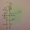
I drew this schematic, its a QRP AM transmitter for 40 meters. Have not built it yet, does it look like it will work? This will feed an IRF510 Final amplifier section that I am building aswell.

Output should be about half a watt from this section, driving the IRF510 Final section and should put out about 5-7 watts.


T23
 

Attachments

  • IMG_20111023_170420.jpg
    IMG_20111023_170420.jpg
    204.1 KB · Views: 197

You need a direct power connection to the collector of the transistor. As you have it now the output of the opamp feeds the collector directly. You should have a direct Vcc connection to the transistor and the output of the opamp should be capacitor coupled to the transistor collector or better yet feed the collector through on side of a small audio transformer's winding and connect the output of the opamp to the other winding and ground. Either way will modulate the power supply voltage causing the RF to be amplitude modulated.
 
There is voltage present at the colector, through the opamp, pin 6 is the power input, the voltage is also present on pin 5 the audio output ,same as the voltage input on pin 6. But if that is not the case, what value capacitor do you suggest to put between the output of the opamp and the colector?

Thanks

T23
 
You could try it like that and see if it works. I have just never seen nor used opamps like that. The DC voltage present on pin 8 MAY possibly power the circuit but running a separate line WILL power it. Also in my experiance with those LM386's they won't work without a cap of around 0.05 uF or so and about 8-15 ohms in series to ground on the output as shown below.As for the O/P cap, anything will do as long as it is at least 1 uF. The only thing affected really is the bass response.

lm386-20.gif
 
Thanks for the suggestions CK, I'll make the ajustments to the schematic and see how it goes, just a side note...How does the cap on the output affect bass response, will increasing the value increase or decrease bass response , volume and modulation? I need this to sound clean but still loud enough.

Thanks

T23
 
More C equals more bass but after you get above a few uF it makes very little difference. Something like a 0.1 uF however will have a noticeable effect on the low end.
 
I think I got it sorted out now, just trying to figure out if I should do the keying in the first stage or the final stage and how I should go about that.


T23
 
Key the final as it will help to minimize frequency drift. Ideally you should have another stage between the oscillator and the final to act as a buffer. This way the load on the oscillator is constant while you key the final. Any change in load is applied to the buffer stage and not the oscillator. Changing the load on the oscillator results in all sorts of unwanted emissions including drift.How you do it up to you but you can always try keying in a low voltage cutoff bias.
 
I was thinking about the buffer stage but the schematic I am using for a base for the final stage on my transmitter does include a buffer but its output is less than my first stage here. The output of the buffer is about 260mw , what I have have now already should do about half a watt.

T23
 
40 meter AM? Biggest problem will be ssb stations thinking you are a shortwave broadcaster. They usually zero beat them in order to use the frequency. Without a buffer you will have some phase modulation and an "interesting" beat note to say the least.

Pipe it through a big amp : )
 
Yeah, I am also trying to fit all this in an altoids tin, too. .I built the fist stage, I tested it, but it did nothing. I think I found the problem though, two cold solder joints... I need to figure out how to do somthing other than toroids for the coils in the final. But first I need to get what I got working...


T23
 
I fixed it, it works now, I put a .1uf ceramic disk capacitor inline with the output to isolate the dc voltage from the RF, no noise in the signal from the tests, but I haven't modulated it yet.


I am using a different transistor than in my schematic, its a 2n4401.

T23
 
Here is the schematic I am basing my final section on, still debating on the buffer stage. I still have to order the toroids ( two FT37-43 ) and the voltage regulator for the Mosfet bias, I think the bias is suppose to be about 2.5 volts, I have found a voltage regulator at radioshack that is adjustable from 1.5 volts to 30 volts with a resistor combination. I think I'll do my keying in the final's 12 volt input line but keep the bias voltage present even when the final is not keyed, or do the keying in the buffer section if I choose to do the buffer section or not.


T23
 

Attachments

  • dds_amp_640x640.gif
    dds_amp_640x640.gif
    24 KB · Views: 236
I have been doing some tests, its been going well, the circut works great. The only thing is that its kinda quiet on the receiver. So I was thinking, should I add the 10uf capacitor across pins 1 and 8 to boost the the gain to 200? 9r should I wait and see how it sounds when the rest is done? I don't think it will fit in an altoids tin with the PA, since I don't know how big ft-37-43 toroids are.


T23
 

dxChat
Help Users
  • No one is chatting at the moment.
  • @ Wildcat27:
    Hello I have a old school 2950 receives great on all modes and transmits great on AM but no transmit on SSB. Does anyone have any idea?
  • @ ButtFuzz:
    Good evening from Sunny Salem! What’s shaking?
  • dxBot:
    63Sprint has left the room.
  • dxBot:
    kennyjames 0151 has left the room.