• You can now help support WorldwideDX when you shop on Amazon at no additional cost to you! Simply follow this Shop on Amazon link first and a portion of any purchase is sent to WorldwideDX to help with site costs.

How to perform the 2sc2999 and Schottky diode swap

Hi George

I saw a few of your old posts on TM1 and it seems a shame you were banned?


Note to Robb: My (UK) callsign G0HZU dates to around 1987. I initially passed the RAE at college in the early 1980s as a spotty student and got the G0 call a few years later.


Getting back to the front end of an early Uniden CB, this radio can be characterised the same way as any radio design regardless of cost.

As I said earlier, the receiver sensitivity can be modelled and predicted fairly well using a simple excel spreadsheet.

These days with the internet you are all spoilt :)laugh:) because of the ease of access to RF design tools :) You can download these in a few mouse clicks.

The tool to use in this case is a cascaded gain/noise calculator.

There's a very basic one here:
Online Calculator .:. Cascaded Noise Figure

You simply enter the gains and losses and noise figure of each stage of the receiver front end and it tells you the system noise figure.

These tools are very useful because the more versatile versions can easily show what changes are fruitful and which will be of little use.

The one I use is very old and it isn't mine to distribute but it has proved a faithful companion.


Here is an image of a very basic spreadsheet for the Cobra 148GTL-DX front end.

2011110401018479236148_excel.gif


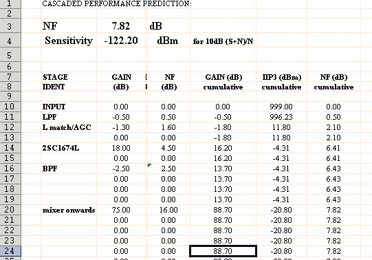
The key things to note are that there are about 2dB of passive loss before the 2SC1674L amplifier. Maybe a couple of dB after it.

Most noteworthy of all is the high noise figure from the mixer stage onwards.

This is typically about 16dB on a mk2 148GTL-DX but I think this can vary depending on mixer LO level etc.

But you can see that there is only about 13.5dB cumulative gain ahead of this mixer on line 19. This agrees with the network analyser plots shown earlier. This means that attempts to swap in a 'super low noise amp' for the 2SC1674L will bring very little reward in terms of added sensitivity.

There is no magic bullet here because the transistor already has a LOT of gain and trying for more gain will mean the risk of instability.

Realistically, any drop in replacement for the 2SC1674L isn't going to be any more than about 1dB quieter.

Even if it's 1dB quieter you don't get 1dB more sensitivity. The spreadsheet tells us that. The reason is because of the noisy mixer after the amplifier.

Putting the RF amp gain UP by 3dB doesn't seem to achieve much....
2011110401019739167148_excel2.gif


Reducing its NF by 2dB didn't make it 2dB better either...?
2011110401013488859148_excel3.gif


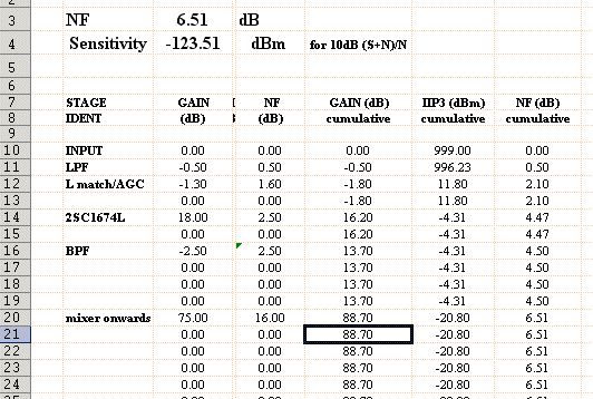
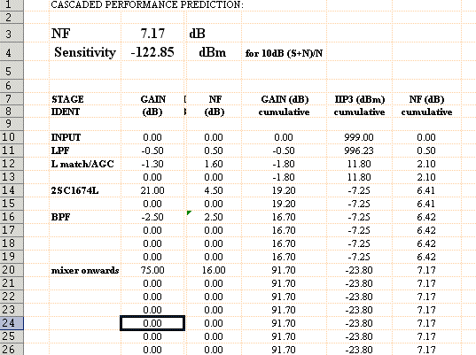
If you managed to find a transistor with 3dB more gain and 2dB lower NF than the current 2SC1674L then the NF drops from 7.8 to 5.6dB. But I don't think this is achievable.

You can see that later Uniden radios switched to a common emitter RF amplifier and FET mixer in an attempt to break away from this design dilemma. They also had to make the circuit work over a much wider bandwidth as well as being more sensitive.

Eg a Uniden 2830 measures out to be over 2dB more sensitive. They achieved this 2dB improvement through redesign rather than just swapping one transistor ;)
 
Last edited:
Hi George

I saw a few of your old posts on TM1 and it seems a shame you were banned?

Sorry i don't know your name mate, but i find your posts fascinating, especially on the weaknesses of the uniden receivers, which i particularly like, more from nostalgia than anything else. shit happens when it comes to me being banned, an occupational hazard when you speak your mind, tell the truth and expose bullshit/ters.

i'm sure i'll live without tm1, lol,

although i admit i still drop by from time to time to read your posts, tim otters posts, bob wa10's posts, nick black spirits posts and neil m's posts, simon 26od004 posts, northern 35's posts amongst a few others, thankfully theres still a few guys to learn from if your shrewd enough to weed them out. i loved josh rogan's style too, although not subtle he was mostly bang on.

i'm afraid i tend to overlook many posts from the numerous "experts" on there,;):LOL::LOL: sadly often they overcome the real techy guys on forums backed up by power of numbers and the unshiftable myths that have perpetrated for more years than i care to remember. i have to admit though, on tm1 i learned the real meaning of the word "amateur", i just hope in the time i was there i helped a few out, but even if i didn't i have some good memories, and a few bad ones, but i tend not to get hung up over tards. Even better i made some real good friends on there, some of whom helped me through tough personal times which i am very grateful for.(y)

good luck on shattering this myth, but i fear if you put every single printout of every single diode/transistor combination and explained why and how it won't improve things, you will still get the, " i hear a difference crowd", sure they do, no-one wants to pay out money on parts, do the time/work for the mod and admit they wasted their time, hacked up a good radio and achieved absolutely nowt. its no different to the "i worked 34 division on my A99 so it must be a shit hot antenna", argument.:headbang:headbang:whistle:


i tip my hat to Robb though, he never gives up on his beliefs, even if they are wrong or Sam Lewis induced,:whistle: sorry Robb, couldn't resist that one.:LOL: you know i'm only messing with you and i know your desperate too learn ( no bad thing), which makes you more susceptible to myth and magic
 
G0HZU,

i think you have more than proved your point.

i must admit that it does feed my ego a bit to know that your findings are in line with what my ears told me. ie: the 2999 makes no appreciable difference, and the schottky diodes make a slight difference on empty frequency noise.

i do not think you should waste any more of your time trying to prove that the specs of the RF amp transistor are not what really matters in these circuits. (common base RF amplifiers)

i have done a few experiments involving changing the value of the emitter resistor in this circuit, and while i dont have the test equipment to prove it; i have found that right about the same point that shows an improvement in sensitivity, the tendency to self oscillate shows up.

the sad thing about all this is that as of right now, we have hit a dead end in our quest to quiet the white noise in the receive of our EPT3600 based radios.

as i said before, if you come up with anything; there are plenty of us who would love nothing more than to breadboard up what you drew in a schematic.

thanks for your time. i imagine this thread will be referenced for years to come when this debate comes up on other forums.
LC
 
Sorry i don't know your name mate, but i find your posts fascinating, especially on the weaknesses of the uniden receivers, which i particularly like, more from nostalgia than anything else. shit happens when it comes to me being banned, an occupational hazard when you speak your mind, tell the truth and expose bullshit/ters.

i'm sure i'll live without tm1, lol,

although i admit i still drop by from time to time to read your posts, tim otters posts, bob wa10's posts, nick black spirits posts and neil m's posts, simon 26od004 posts, northern 35's posts amongst a few others, thankfully theres still a few guys to learn from if your shrewd enough to weed them out. i loved josh rogan's style too, although not subtle he was mostly bang on.

i'm afraid i tend to overlook many posts from the numerous "experts" on there,;):LOL::LOL: sadly often they overcome the real techy guys on forums backed up by power of numbers and the unshiftable myths that have perpetrated for more years than i care to remember. i have to admit though, on tm1 i learned the real meaning of the word "amateur", i just hope in the time i was there i helped a few out, but even if i didn't i have some good memories, and a few bad ones, but i tend not to get hung up over tards. Even better i made some real good friends on there, some of whom helped me through tough personal times which i am very grateful for.(y)

good luck on shattering this myth, but i fear if you put every single printout of every single diode/transistor combination and explained why and how it won't improve things, you will still get the, " i hear a difference crowd", sure they do, no-one wants to pay out money on parts, do the time/work for the mod and admit they wasted their time, hacked up a good radio and achieved absolutely nowt. its no different to the "i worked 34 division on my A99 so it must be a shit hot antenna", argument.:headbang:headbang:whistle:


i tip my hat to Robb though, he never gives up on his beliefs, even if they are wrong or Sam Lewis induced,:whistle: sorry Robb, couldn't resist that one.:LOL: you know i'm only messing with you and i know your desperate too learn ( no bad thing), which makes you more susceptible to myth and magic
spanking.gif
 
MY 2 Cents ......

With the very wide results that most of us get in the REAL world of radios
IF it works for you have at it .....

I know what I GOT on MY radio but then again another radio may or may not have done much of anything.

COPMMENT on the FT-100 ....

Mine is about 10 years old it is ONE FINE RADIO however don't over heat it you will not get a 2nd chance .....

For many years in worked in defense electronics in R&D both in Clearwater microwave and in the field at the KSC and engineering in UHF radio systems for several other companys as a tech before going to public safety ( SHERIFF ) back almost 20 years ago now .....

SO .....

I fully understand what is going on however given the variances in production radios let the user determine for himself if it worked for him ...


Photos attached microwave group ( I'm the short one on right ) at pad 39B Feb 1982 sperry micorwave R&D field lab. NOTE shuttle being rolled out to pad 39A in background.

FT-100D I own ..
 

Attachments

  • sperryradadksc1982.jpg
    sperryradadksc1982.jpg
    33 KB · Views: 125
  • ft100d2.jpg
    ft100d2.jpg
    140.6 KB · Views: 125
Hi George

I do like TM1 and it's one of the few forums where everybody seems to get along and can have a laugh etc.

There are a few stubborn myths and beliefs on there and some obsessive collectors and I've learned not to be too harsh about certain radios because it can upset some of the posters :)

Regards
Jeremy

G0HZU
 
the sad thing about all this is that as of right now, we have hit a dead end in our quest to quiet the white

noise in the receive of our EPT3600 based radios.

as i said before, if you come up with anything; there are plenty of us who would love nothing more than to

breadboard up what you drew in a schematic.
LC

Hi LC
In terms of white noise there's two main issues at work here.
There is the obvious 'noise above thermal noise' due to the system noise figure and this limits sensitivity. However, with today's noisier bands I think an 8dB system noise figure should be fine.
But there is another issue with the Uniden radios and that is how they do the AGC.
On most Uniden radios the AGC acts in two places. At the first IF amplifier and also at the AGC diodes at the front end.
On radios that are dual conversion on AM (like my mk2 148GTL-DX) the AGC acts at the second mixer as well as the AGC diodes.

The basic idea is the early part of the AGC range acts on the IF amp (or mixer) stage and then for bigger signals the AGC diodes start to come into play as well.

It's arranged like this to try and preserve the larger signal to noise ratio of bigger signals and make the radio sound cleaner as signals get deeper into the AGC range.
However, for these radios it doesn't actually preserve signal to noise as much as hoped. This means that on AM/FM the radio will sound hissier than it should as the signals get bigger and the AGC acts more and more.

Changing the front end amp will do little for this because it's the falling gain vs rising noise characteristic of the variable gain IF stage (or mixer) that is causing the radio to 'stay noisy' as the AGC starts to level the gain as the input level gets bigger and bigger. This is all tied in with the way the radio is designed and to do something about this would involve a fair few mods.

One thing that is annoying about the newer radios is that they have copied the crude AGC system from these early Uniden CBs and stuck with it. This means even the newer radios will show this noise problem.
I could come up with ways to improve the AGC characteristic but it would mean quite a few changes and there is the risk of making the AGC loop go unstable unless a specific set of mods are done for each model of radio.

The easiest way to prove this point on my mk2 Cobra 148GTL-DX is to disable the AGC and look at the S/N ratio on FM mode for signals across the equivalent of the first 20-25dB of AGC range.
On the standard radio (with AGC still active) the radio remains quite hissy as the generator is cranked up.
But with AGC removed the hiss falls away steadily as the signal gets bigger. A marked difference.

I've seen people blame this problem on the PLL (they say it's noisy?), on the CPU in radios with CPU and on the audio stages and also on the receiver front end noise figure.

In reality, the noise is a byproduct of the AGC system as it isn't designed to preserve S/N ratio very well.
 
I'll try and knock up a quick youtube video of what a Cobra 148GTL-DX sounds like on an S9 signal on FM.

You will all be familiar with the hissy noise you get on the carrier.


Now an S9 on the meter is approx -73dBm and this is a big fat signal. Uber signal to noise ratio yet the 148 sounds hissy...

Is it the PLL? Is it the AF stages? is it the 2SC1674L amplifier?

No. It's the AGC.


To prove this I'll disable the AGC in real time and you guys are going to think I cheated and turned up the squelch because that hissy noise is gone!

Just a nice clean carrier is heard.
 
Here's a link to the video

Cobra 148GTL-DX AGC HISS - YouTube

I assume this is the white noise you are referring to?

If the AGC system had a better design then the radio would sound almost as good as it does with no AGC at an S9 signal because the S/N would be preserved better.

FM doesn't really need AGC as it uses a limiter ahead of its detector (all within the FM chip) so this test can be carried out on FM.

Obviously I couldn't do this test on AM as the lack of AGC would cause massive overload and distortion. But by disabling AGC on FM it shows just how much the AGC fails to preserve the S/N ratio.
 
interesting vid GOHZU,
the 148's fm hiss is annoying, the stalker9fdx is imho even worse with poorer sensitivity, the grant sounds less hissy and slightly more sensitive to me,

in the past i presumed the main differences between chassis were the two extra tuned circuits between LO and first mixer in the grant and the missing stage in the stalker,
theres also a small difference in rf amp biasing but playing with that never gained me any benefit,


a local used to mod the stalkers by increasing the LO level into the mixer to make the receiver seem to be more sensitive/meter act more like a 148, i don't know if it actually improved the receiver or made it worse.
 
Hi Bob
You have confused me slightly because I don't think the Stalker will be as affected by the AGC issue on FM.

This is because the Stalker (and the mk1 Cobra 148GTL-DX) don't use any AGC on the second mixer or 455kHz IF stages.

The S meter gets driven via the AM/SSB path so the AGC at the AM/SSB IF won't degrade the S/N ratio on the FM path until the AGC diodes are activated. This needs a big signal.

So this radio should show better quieting on FM.

But I haven't used a Stalker for many years so there might be some other reason for the hiss noise you are hearing.
 
This has been a great thread so far!

I have tried the 2SC2999/Schottky diode swap in several different chassis, and and like G0HZU's testing shows, there was really nothing gained from this swap, at least nothing I could tell by ear. I have a few of the locals swear by it, saying that there's a BIG improvement, but hey, whatever floats their boat. I have done some swaps for a few of the locals here at their request, but I'm not a real big fan of this swap and the "hype" it generated.

I personally believe that the best thing that can be done is to have the RX properly aligned and leave it alone, no need to change diodes and transistors if there really isn't any real benefit. Perhaps I am old school, but "if it ain't broke, don't fix it."

Thanks G0HZU for doing the testing, I've found it quite interesting!

~Cheers~
 
hello G0HZU,
you would have to compare the grant cobra and stalker side by side to hear the difference and see the difference on the s-meter with weaker signals between the 3 similar radio's,

the fm metering on the stalker is not my favourite, you get more needle bobbing with deviation and usually three signal peaks as you move the clarifier.
 
This has been a great thread so far!

I have tried the 2SC2999/Schottky diode swap in several different chassis, and and like G0HZU's testing shows, there was really nothing gained from this swap, at least nothing I could tell by ear. I have a few of the locals swear by it, saying that there's a BIG improvement, but hey, whatever floats their boat. I have done some swaps for a few of the locals here at their request, but I'm not a real big fan of this swap and the "hype" it generated.

I personally believe that the best thing that can be done is to have the RX properly aligned and leave it alone, no need to change diodes and transistors if there really isn't any real benefit. Perhaps I am old school, but "if it ain't broke, don't fix it."

Thanks G0HZU for doing the testing, I've found it quite interesting!

~Cheers~

1+
 
Thanks :)


I found the 959 radio here

http://www.cbtricks.com/radios/galaxy/dx959/graphics/dx959_sch.pdf

As LC says this one is very similar to my mk2 148GTL-DX but I spotted they have included a very basic upgrade to try and offset the noise seen in my hissy 148 video.

If you look at the top of the schematic near the centre you will see R26 and D7.

D7 gets biased from the AGC line via R26 and acts like a crude variable attenuator and this reduces the gain of Q9 by damping the tuned circuit of L2.

This mod will therefore share some of the AGC action with the mixer at Q8.

This will help preserve the S/N ratio better so these EPT radios won't be as hissy as the mk2 148GTL-DX on FM and AM.

I suppose I could try fitting the diode attenuator/switch to a 148 and test it but there's a risk the AGC will go unstable or introduce distortion at certain signal levels on big AM signals. The D7 mod is quite crude but it's probably quite effective. I'd still expect some hiss though and I would have thought they would have modded the 455kHz stage a little more elaborately to give a better AGC action on AM and FM.
 

dxChat
Help Users
  • No one is chatting at the moment.
  • @ Wildcat27:
    Hello I have a old school 2950 receives great on all modes and transmits great on AM but no transmit on SSB. Does anyone have any idea?
  • @ ButtFuzz:
    Good evening from Sunny Salem! What’s shaking?
  • dxBot:
    63Sprint has left the room.