• You can now help support WorldwideDX when you shop on Amazon at no additional cost to you! Simply follow this Shop on Amazon link first and a portion of any purchase is sent to WorldwideDX to help with site costs.

Construction of 140W PEP EB63 amplifier + Low-Pass Filters

Been working a lot and getting lots of gigs.. progress has been slow, but I've got the filters tuned (I just mounted them one by one on a good ground surface and hit them with a signal) and I developed a plan for constructing the free-standing filter set as a whole:

LPFlayoutWEB.jpg


There will be a copper bus on each side of the row of filter boards, each connected to an so-239. Each filter input and output will be connected to these buses via relays. I came to the conclusion that this design is the only workable one due to the fact that long runs of wire or coax connecting everything drastically hurts the performance due to impedance mismatches and losses. I was also unhappy with the losses generated by trying to avoid relays by running the signal directly through a 2-pole 6-pos. switch. I'm actually planning on mounting each filter board vertically rather than flat to cut down further on the footprint and the signal path length.

I'm also waiting on a heatsink for the EB63a and 2 enclosures.
 
Any updates??
I've been thinking of building one as I have most of the compnents sitting in my shack, Just need the circuit board and transformers as well as the filters.
 
I've received a project box and I'm in the process of drilling it for the filters.. I also have found a good heatsink for the amplifier, but I haven't drilled and tapped it yet. I just got back from a weeks vacation to Gulf Shores AL, and working two jobs has been keeping me busy lately. With any luck I'll have these things finished by this time next month. It'll be sweet to see how the amp performs..
 
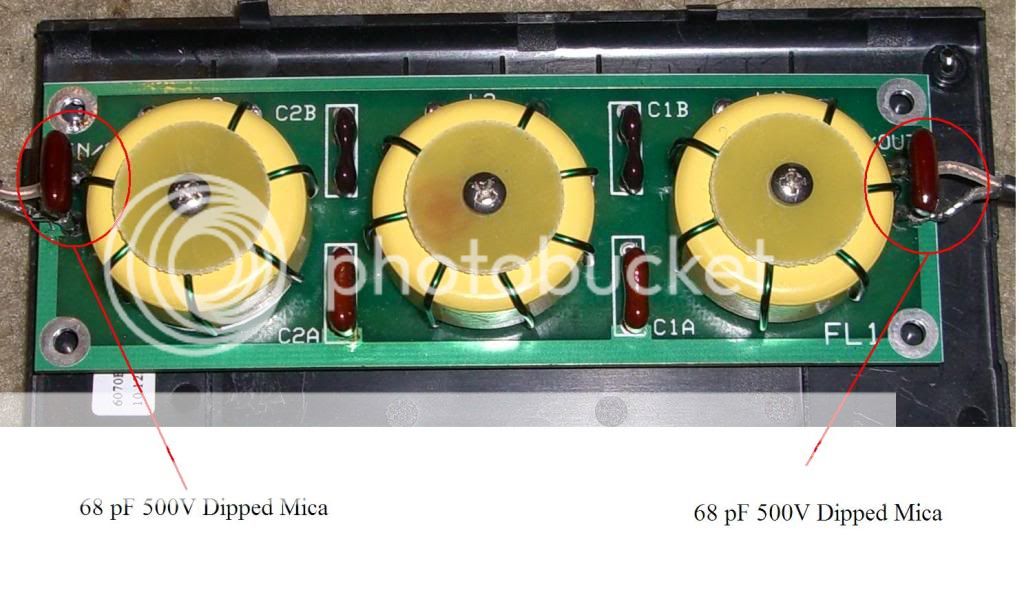
I just wanted to share a recent experience and a major improvement I discovered while building this set of low-pass filters from CCI. In the base configuration (L-input 5-pole) the input impedance varied a good amount over the bands that the filter will be used on, resulting in a highly variable input SWR. Here I'll be discussing the 10m filter since it's been the main subject of my experimentation. The input SWR of the 10m filter as constructed in accordance with the supplied instructions was perfectly usable from 28.0MHz to 29.3MHz, but the power handling capability needed to be derated at the bandwidth edges as the input SWR approached 1.8:1, indicating an impedance mismatch which seemed to overheat one of the capacitors (in the photo below it's the lower right-hand mica cap in the central group of 4) to the point of burning out. In it's original configuration the maximum continuous (100% duty for 10+ minutes) power I could pass through the filter was around 75W without eventual damage. These filters are rated to 300W PEP, which is actually conservative since the toroids and capacitors should allow up to 500W PEP if optimized properly, so by my logic they should be able to handle at least 120W continuously. I felt that there was some need for improvement, so I modeled the circuit in ELSIE so that I could play around with various configurations and view their responses and parameters.

Here's a graph of the cutoff (red) and vswr (blue) of the 10m filter as supplied by CCI (based on a schematic from an ARRL text):

vswrandcutoff5-pole10mLPF.gif


The swr curve has some nice low points that kind of roughly correspond to the bands that the filter will be used on (10/12m) but they also peak above 2.0 at certain points across the bandwidth. In real-world usage these peaks fall closer to the bands of operation than I'd like, resulting in somewhat high SWR at the edges of these bands. As I'm looking for peak performance across the widest possible bandwidth I felt improvement was possible and necessary.

A primary interest of mine was to keep the core configuration of the filter intact, so I didn't want to alter the cap values or the inductor values of the original configuration. That left the option of adding more components.. by adding 2 more capacitors I ultimately ended up with a 7-pole filter with much better input impedance values and sharper cutoff.. both good things! Plus the finished mod was about as easy as it gets.

As can be seen in the original schematic the main capacitance consists of 118pF shunted to ground. This is comprised of a 100pF cap in parallel with an 18pF cap on the board itself:

5-poleschematic.gif


I found that adding two more capacitors with values roughly half of the originally installed capacitance (118/2, or ~68pF in this case since I had quite a few 68pF caps on hand) at the input and output of the filter resulted in better performance across the bandwidth with much less loss, resulting in full power-handling capability (easily handles 120W+ continuous without major heating):

7-poleschematic.gif


Here's the curves for the improved 7-pole filter. You can see that the input vswr no longer peaks nearly as high near the intended bands of operation while the cutoff is sharper. The real-world performance mimicked the software plots almost exactly:

vswrandcutoff7-pole10mLPF.gif


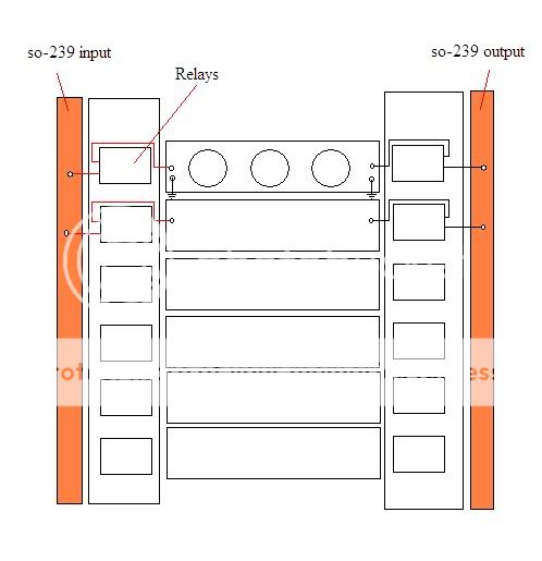
Here's the finished filter. The added caps are simply soldered across the input and output connection points:

filterfinishedannotated.jpg


This logic can be applied to all of the filters. I found that adding 2 more capacitance poles with values of roughly half of the originally installed capacitance values made for a much more user-friendly and better performing filter regardless of the intended band of operation. I'm certainly no expert, just a hobbyist, so I hope that this information works for others with similar results.
 
Excellent and very nice! Another thought is gain compensation if you plan to use this on a few different bands which would be apparent from the use of your several low pass filters.
 
Thanks, and sorry I missed these posts. I've been very busy with work lately and that's left me with pretty much zero time for hobbies. This project is currently on the back burner with everything else hobby related. I've got everything needed to complete the project except for time.

Regarding the question about the results of the added feedback network, I have not yet powered the amp so I can't answer that yet, but I will say that this exact feedback network is used in many broadband HF amps using MRF454s pretty much verbatim, so there really is no reason why it wouldn't work here.

It's my plan that the series inductors in the feedback network will provide some rudimentary gain compensation, certainly not as good of a solution as a transformer but it should be quite a bit better than nothing.

Thanks for the update. I think I'll order the parts after lunch today. I start extended holidays tomorrow so I'll have time to build 1.
 
why did you add the vk200 in the feedback path?
you do not need it at all!
make the resistor a 82 ohms it will work better as I found out
4z4rb
 

dxChat
Help Users
  • No one is chatting at the moment.
  • @ Wildcat27:
    Hello I have a old school 2950 receives great on all modes and transmits great on AM but no transmit on SSB. Does anyone have any idea?
  • @ ButtFuzz:
    Good evening from Sunny Salem! What’s shaking?
  • dxBot:
    63Sprint has left the room.
  • dxBot:
    kennyjames 0151 has left the room.