What is a single tube rated for roughly. Someone brought over an amp that has 3 driving 8. I got it up and running. Not sure what the problem was really it works on low and hi. Low does about 500 pep. Hi does around 1400 top end. I'm sure that's more than what those tubes are rated for for sure. But I never worked on a sweep tube amp. And yes, the caps do not have bleeders. But it will before it leaves. I hate when they do that.

You are using an out of date browser. It may not display this or other websites correctly.
You should upgrade or use an alternative browser.
You should upgrade or use an alternative browser.
-
You can now help support WorldwideDX when you shop on Amazon at no additional cost to you! Simply follow this Shop on Amazon link first and a portion of any purchase is sent to WorldwideDX to help with site costs.
2057's
- Thread starter Crusher
- Start date

Thanks, Its up and running. But its not optimized. Has a lot of capacitance on load, but Tune side is wide open at absolute minimum. It has flat stock and everything is bolted and then soldered. A lot of work to optimize for a few more watts. Its already doing more than it should.
Yes the M2057 is a heavy duty 8950 with about 8 more watts dissipation = 32 for the 8950 and = 40 for the M2057.
Are the tubes branded GE or Maco?
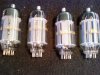
GE ran some M2057`s for Maco and put there brand on them, these were never intended to be used in TV sets LOL.
( see picture below)
73
Jeff
Are the tubes branded GE or Maco?
GE ran some M2057`s for Maco and put there brand on them, these were never intended to be used in TV sets LOL.
( see picture below)
73
Jeff
Attachments
All M-2057 tubes were made at the GE plant in Owensboro Kentucky. I use to think it was just a beefed up 8950 but the truth is GE didn't have to beef any tube up. Maco somehow talked them into placing the GE 8908 sweep tube inside an envelope with a 12 pin Compactron base. This happened in 1976 when sweep tube sales were dying so GE took any large volume sales they could find.
Notice the "Peak Positive Pulse Plate Voltage" rating on the M-2057? That's a direct carry over from the 8908 sweep tube data. That 7500 volt rating can only occur with this tube in horizontal output applications when the electron beam is cutoff in the blanking process of the scan.
GE also made tubes for a large number of equipment manufacturers such as Heathkit, Tram, Browning, Maco, Sonar, and many others. You can spot a rebranded GE tube by the 188-5 code stamped on the tube. That is the old Kentucky Radio tube facility that GE purchased and the code they put on all tubes made there.
Last edited:
Maco somehow talked them into placing the GE 8908 sweep tube inside an envelope with a 12 pin Compactron base. This happened in 1976 when sweep tube sales were dying so GE took any large volume sales they could find.
[/QUOTEP]
I learned something, as you i alway thought the M2057 was a heavy built 8950.
73
Jeff
This peaked my interest, and I went searching for more Info.........found some postings on lists.contesting.com from guess who?
Will Matney.
As some of the older guys here will remember he, was a member here at one time, said he used to work for Maco back when they were building amps.
This was regarding a Amp design that was posted in a issue of QRX.
He and Tom, W8JI were talking about using sweep tubes in Amps......
Here are some Quotes:
Tom W8JI:
Will:
</>
Interesting reading.
Full Thread:
[Amps] QEX Innovative Tube Linear?
73
Jeff
Will Matney.
As some of the older guys here will remember he, was a member here at one time, said he used to work for Maco back when they were building amps.
This was regarding a Amp design that was posted in a issue of QRX.
He and Tom, W8JI were talking about using sweep tubes in Amps......
Here are some Quotes:
Tom W8JI:
>>I just looked at the curves for several sweep tubes
>>including the ones I mentioned, and they didn't start to
>>bend until around 250 Vdc and below. They were flat from
>>there on up in voltage until the maximum permissable anode
>>voltage rating. Running them just at or below the maximum
>>permissable anode voltage would be recommended. Some
>>designers of the past tried to run them at a much greater
>>anode voltage than what the spec sheets say is permissable.
>>I'll try to post the different maximum anode voltages later
>>this evening.
>
>Do you actually have an application sheet for these tubes in
>linear amplifier service Will?
>
>73 Tom
Will:
Only for the 8950 and M-2057 (or Y-2057) as they were the only ones that GE
said were for RF amplifier service. The M-2057 was a custom tube that was
manufactured by GE. They took an 8908's guts and placed them in a 12 pin
compactron base which was what a GE engineer told me. The only specs I have on
the 8908 is in a GE tube applications book. I have the GE application sheets on
the 8950 and M-2057. All the other sweep tubes were based around TV horizontal
output service, however the maximum DC anode voltages still apply. The M-2057
matches several other sweep tubes at 990 Vdc. The 8950 was 800 Vdc. If I
recall, the curves on these didn't drop off from a flat line until around 100
Vdc anode voltage. Above this, the line was pretty flat (gradually increasing)
up to the maximum anode voltage that was shown on the graph. I think you can
download the 8950 PDF from Richardsons along with a few other sweep tubes. The
M-2057 sheet I've had for years. These are the same application s
heets from the 3 ring binder book from GE.
Best,
Will
</>
900 Vdc is the design-maximum by GE, I'm not quoting RCA. Read the GE sheets
and you'll see the difference. Most sweep tube curves don't show the
design-maximum anode voltage. They stop about 1/2 way or a little below.
Quote from all GE application sheets including the M-2057 and 8950;
"Design-maximum ratings are limiting values of operating and environmental
conditions applicable to a bogey electron tube of a specified type as defined
by its published data, and should not be exceeded under the worst probable
conditions".
"The tube manufacturer chooses these values to provide acceptable
serviceability of the tube, making allowance for the effects of changes in
operating conditions due to variations in the characteristics of the tube under
consideration".
"The equipment manufacturer should design so that initially and throughout life
no design-maximum value for the intended service is exceeded with a bogey tube
under the worst probable operating conditions with respect to supply voltage
variation, equipment component variation, equipment control adjustment, load
variation, signal variation, environmental conditions, and variations in the
characteristics of all other electron devices in the equipment".
End Quote.
My guess is they lowered the anode voltage and current on each tube to help
with the IMD problems. Running sweep tubes at 1100 to 1200 Vdc sure isn't a
good idea as that's over their maximum rating. Around 900 Vdc at the most for
tubes like a 6LF6, etc. Smaller sweep tubes (6LQ6, 6JE6, ect) ought to be ran a
little less. I ran a quantity of eight 8908's or M-2057's G-G to get 1500+ kW
PEP out of a sweep tube amp using 900 Vdc on the anodes. They were capable of
300 watts PEP each being grid driven. The 8950 or 6LF6 was some amount less,
around 175 to 200 watts each grid driven. I built one using two of the EL519's
(6KG6A), and the most I could squeeze out of that little grid driven amp was
about 300 watts PEP, so figure them at 150 watts PEP out each maximum. Running
them G-G would probably yield a less on AM, but about the same with SSB. That's
just from my expeirence with them. I'd like to see the article my self and see
what tubes and voltages they used.
Best,
Will
Interesting reading.
Full Thread:
[Amps] QEX Innovative Tube Linear?
73
Jeff
Is this amp the POW KW+ ? Or is it the Maco 2 piece.
I have 2 POW KW+. One with original but new M-2057. The other I re-tubed to 35LR6 about 13 years ago. I also have the 2 piece Maco.
On a RMS reading average Coaxial Dynamics RF Directional Watt Meter (bird 1KW element) The M-2057
tubed POW does exactly 1200 Watts average. Original brass flat tank 4 turn coil.
The re-tube POW a bit over 1100 watts average with a 1/4 copper tube 4 turn coil. At the time did not have an inductance meter or knew the value of H required. The original brass coil only gave me 1KW. Trial & error the 1/4 copper tube coil 4 turns worked better.
The 2 piece Maco only does 1KW with M-2057. Possibly I have to simply tune the tank coils. I only used it a couple of times in the last 16 years. The tubes are packed away with more M-2057's in a water/moisture proof container.
As a side not. 6LW6/26LW6/36LW6 appear to be quite close to the 8908/M-2057.perhaps 6LF6 ?
I was thinking of using an etching lazer to cut the internal connection on the LW6.
If it works & the tube still useable. would make a really good grounded grid RF sweep tube ?
Looking at the tube data. 8950 is simply a 6LX6 or 26LX6 with a 13v filament.
Best
You will probably need around 25 VDC of grid bias to use that kind of plate voltage. At 1400 volts on the plates, your zero signal resting plate current will probably be higher than your running plate current.What is a single tube rated for roughly. Someone brought over an amp that has 3 driving 8. I got it up and running. Not sure what the problem was really it works on low and hi. Low does about 500 pep. Hi does around 1400 top end. I'm sure that's more than what those tubes are rated for for sure. But I never worked on a sweep tube amp. And yes, the caps do not have bleeders. But it will before it leaves. I hate when they do that.
1,000 VAC into a capacitor input filter (no choke) will give you that voltage. In order to set up your grid bias, you should have a 0-50 volt negative bias supply that's adjustable. Then use a Variac to slowly increase your plate supply voltage from about 700 volts upward to your goal of 1,400. Key the mic or trip the T-R relay switch to complete the plate voltage circuit. Watch the current meter. Slowly raise the grid bias voltage upward to limit resting plate current to 1/10th of the full plate current. Repeat the steps until you have the bias set for the tubes. Test one tubes at a time to get the best bias voltage.
You will probably have to build a bias supply to give you negative grid voltage. With sweep tubes, you really don't need separate regulator bias channels, but it helps. There are plenty of DC circuits available that you can add 10 potentiometers to adjust each tube separately. Then you have truly matched set of tubes with separate bias channels.
8908's have 12 volt filaments. You can get a 24-volt filament transformer and hook up the tubes series-parallel, and use the secondary to run your bias supply.
I would change the tube configuration to increase the efficiency of the driver and final relationship. 1 8908 driving two, driving six tubes is a badly inefficient method of connecting tubes. If you have a large enough plate transformer, you can use one 8908 to drive three, and run 10 tubes in the final. Or you can use a pair of 8908's running grid driven, and anywhere from 6 to 8 x 8908's in the final. You eliminate the 2nd driver stage and still tap the feed-through power from the driver through the finals. 8 tubes in the final can get you 1,000 watts RMS output. PEP/peak or "swing" is 90% BS and another 90% hype. Your radio determines the "swing" in your thing, and RMS is what walks the dog, punches through the pile-ups, and squashes the local mud-ducks. Peak or PEP on these "peak" reading watt meters is done by a battery, a circuit board, and a capacitor. You can't measure it directly.