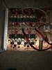
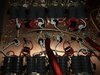
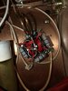
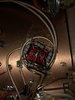
Let me say first of all, I’m no tech. I don’t claim to be. I’m a hobbiest with an interest in modifying and building. This is the first amp protect I’ve ever taken on. I built this 16 pill amp from the plans found on this forum. They are the exact plans that I’ve found on other forums. The only thing I’m not understanding about these plans is it doesn’t call for any kind of variable capacitor for the input side, therefor I have clue how I would tune this amp. When I finished the amp, I put two 4 gauge wires on the power bus to just try it out with radio drive. I got no output on the meter whatsoever. Like an idiot, I turned my Texas star 400 on to see if it would do anything. It popped the 4 resistors on the Teflon wrap on the output transformers. Any help would be appreciated. I’d like to try to figure this out before I send it off to be looked at. Thanks!!

You are using an out of date browser. It may not display this or other websites correctly.
You should upgrade or use an alternative browser.
You should upgrade or use an alternative browser.
-
You can now help support WorldwideDX when you shop on Amazon at no additional cost to you! Simply follow this Shop on Amazon link first and a portion of any purchase is sent to WorldwideDX to help with site costs.
16 transistor project
- Thread starter mattsowders1989
- Start date

Hello Matt,
The first thing I noticed is you have the phase on the RF transformers "bucking" or 180 degrees out of phase. Pay attention to which side of the input and output transformers are grounded and what side is connected to a combiner or spliter. If you compare it to the schematic or other working circuits you'll see you have some of these connections reversed.
The first thing I noticed is you have the phase on the RF transformers "bucking" or 180 degrees out of phase. Pay attention to which side of the input and output transformers are grounded and what side is connected to a combiner or spliter. If you compare it to the schematic or other working circuits you'll see you have some of these connections reversed.
Well, to keep it simple - when you have to choke off RF - don't place the piece on the foil - use a "land" either as a separate piece of PCB board you solder onto the choke, and then adhesive to the foil backplane - that's fine - but mixing RF grounds is asking for trouble...

Lots of builders just "dremel" a land or two that isolates the pad for mounting to INSULATE it from board ground or Backplane influences and let RF ground tie off the choke / pipes...A big square to isolate the land from the active surface - essentially forming a insulator island and solder the pipes core board to it.
Lots of builders just "dremel" a land or two that isolates the pad for mounting to INSULATE it from board ground or Backplane influences and let RF ground tie off the choke / pipes...A big square to isolate the land from the active surface - essentially forming a insulator island and solder the pipes core board to it.
Yeah, need to, else it (RF) will ruin your whole day...
Look for this work, you'll see what I mean...
https://www.worldwidedx.com/threads/fatboy-6-pill.233120/
Notice the lands they use for the input are tied off - they are simple squares of PC board glued to the backplane and they serve as standoffs - this can help you in your design to isolate sections from the backplane that although may not make a physical true connection - they are close enough that RF can "arc" as weld to it and use it as new path you don't want...
ah!!! i see. i will do that. Thanks. What able input tune? how do i change that? the plans did not include any variable cap. also, do my combiner and splitter look like they are wound right? ive never made them before.
To describe it, I'm not that guy. But to keep it short and sweet - your stacked tubes are the "secondary" towards the power transistors. The Winds are the Primary.
In light of transformers - you have "step up" - "step down" and Isolation - mean what they say- a way to also look at this is to say "impedance Network" "step up" - "step down" and Combination - again a way to look at taking one ohmic reactance result to another - it's done with pipes, ferrites and the winding methods used.
So if you think in relation to that - your length of pipe - folded over - is the winds your Base leads need - the Ferrite cores are a lot like the laminate and the winds thru the pipes - is where your power goes in.
Once the lengths of pipes and their chokes are done - the Secondary is done.
Primary? That is your tuning effort - the winds come from the combiner/splitter (input) to your Base's Pipe stack - the pipe stack is secondary, the winds are the primary to it - you can think of raising the impedance by raising the number of turns or winds you have to use to "meet" your expectations - it's science but also a labor of love - you may find yourself doing a lot of winds as trial and error - so best to use a template (Sigh) but also from that template comes the experience - and start out with more than enough winds - one or two extra - per "pipe and core stack". Lots of people think a tuning cap is the way to go, I wish I could say yes to that but what they miss is the direct coupling match tune they can obtain by working and doing the effort of hand tuning the stages and section of the amp. The efficiency of the mutual coupling without having the variable is satisfaction in itself.
Output side is the same way, only you work in reverse - you are taking the power transistors own output into a series of pipes (a transformer wind so to speak) and the wire winds within take up the energy from the pipes - and transfer it to the combiner - which is also taking in all the others. So you are doing a step up process - so you're taking the power developed from Collector To Emitter - thru the pipe that is also sending in DC voltage - and let the winds pick up the RF energy and since the winds are not directly connected to the DC voltage - they accept RF and take it's energy out of that stack of pipes and ferrites - leaving the DC behind for the power section of the transistors.
Now remember that you're dealing with proper impedance matching of the base to accept power and the output has to have it's level of impedance matching to develop and send that power out. So there will be a series of circulating currents of power running thru those output pipes - so it has to be correctly done so those currents are kept in phase relationship to each other - then that power is extracted off the pipes thru the winds. The output impedance the transistors work best in is slightly higher than the input impedance - so that is why the pipe lengths for input to output are different - its' a ratio. And why the pipes on the output side are or seem to be - twice as long as the input side - that's is for the very reason of propagating RF at a SPECIFIC range of frequencies - those pipes and ferrites and winds have to be a specific length to accept the energy developed without losing it in poor phase relationship (out of phase by a level of INCEPTION Start to End - sort of thing) so they appear as more like a tuning fork ringing at an octave of the other.
So in a way, you are making a series of or steps for - impedance - like a power transformer would for the input power - split, pared down into the sections - equally - then amplified - sent thru the output pipes and its' impedance - thru winds in those pipes, cores stack - back up to a step of impedance that allows the stage to be combined with others - summed into one single output of specific impedance.
A tuning cap is a quick and dirty way to fix a messy problem - but if all things are made equal - the effort is placed in similarity and duplication - then the problems go away or are easily solved because of the facts of one section goes bad does affect others but you arrive to the solution by seeing the results in your work and anything out of place? Just realign - put back in place and move on.
Another factor of "tuning cap blues" are just that - they cover up a messy stain or mis-match caused by poor wind and or tube lengths that were done for one type of transistor that is now no-longer made - that design is an orphan - best to start all over but for many that is not possible. So the tuning cap makes up for that orphaned design but you lose the power efficiency the amp design when properly done - can really do.
So much for "short and sweet"...
Last edited:
matt,
look at the board layout you posted, and you will see that the side of the input and output transformers that is closest to the "pill" are mounted to what are known as 'pill strips'. they are pieces of copper pc board that have been cut and they are glued in place on top of the main copper board (which is your ground).
there will be a cut on each of them and you can see that there is a capacitor across this cut. on the input side, its a 330pf cap. on the output side it's a 1000pf cap.
you solder your transformers to the 'pill strips' and then leave the other side floating, as in not touching anything. i would use a piece of phenolic or other insulating material here just for mechanical support, but these ends of the transformers should not touch anything on the copper board.
from your pics, i don't see any pill strips at all. can you post a pic of this section?
also, that 330pf and the 1000pf caps get soldered to the transformers themselves and not to the pill strip as shown in the diagram.
building a 16 pill amp for your first attempt is a daunting task. most recommend building a 4 pill first so you can get used to how they need to be tuned before stepping up to the big leagues where mistakes cost in the hundreds of dollars.
we can get to input tuning later. let's see that amp key up and make power before we worry about that. from the looks of it, you've got a lot of unsoldering to do.
LC
thanks everyone. im going to go over everything you guys mentioned and ill get back with you guys. thanks
Shadetree Mechanic
Delaware Base Station 808
Just curious if you ever got this going or what you did to make it work.thanks everyone. im going to go over everything you guys mentioned and ill get back with you guys. thanks
Shadetree Mechanic
Delaware Base Station 808
Shadetree Mechanic
Delaware Base Station 808
16 pill and tuning info bump. I am going to go back and read it again. Now that I am digging into my own amp, this is starting to make sense.
Last edited:
i did get the amp going. had help from a friend who has built them in the past.