• You can now help support WorldwideDX when you shop on Amazon at no additional cost to you! Simply follow this Shop on Amazon link first and a portion of any purchase is sent to WorldwideDX to help with site costs.

455Khz. Ceramic filters & bleedover in Exports...

Hello All: This thread is most interesting and needs to be covered the filter bandwidths vs receiver noise, and received signal audio quality of SSB received signals.

Years ago I installed the IF crystal filter in my 148 radio and noticed somewhat quieter receive, didn't know if it was the narrower IF Filter, or maybe some loss in the filter.

My Yaesu 902DM only has a SSB IF filter, that made AM a little hard to use as I had detune the receiver frequency to clearly hear the AM stations.

I wouldn't mind paying for a better IF Filter for my Stryker 955 if there was a proven IF Filter modification out there. Even if the cost of the upgraded IF Filter Mod pushed the cost of the radio close to a new Ham Radio I would still try it.

Again great thread.

Jay in the Great Mojave Desert
 
In case it was missed not sure why they all end up with the person I'm quoting comments VVVVVVV.

Yep I definitely misspoke I did in fact mean 10.7 crystal filter I did pull one from an older cobra or something and swapped it in think better part not made in china. Didn't really notice much change. So yes I would like to narrow both the 10.7 and 455 if it will help. Also yes I can't get a schematic for it either I've called and emailed Rci with no luck its shares similarities with both the rci6300f 150 and the rci2950dx.

Also has no one here watched any of lescomm videos on line about narrower 10.7 filters ?
 
Well I'm going to jump in here and add something not too many others are reviewing...

The AGC side of this...

Many people think that with the advantages of the newer filter addition - now we have a quieter receiver...

Well, Yes and No.

In a Galaxy Radio? AGC is derived from the Quad Op Amp chip IC1 AFTER it gets amplified by the S/RF Meter Buffer Amp then onto Pins 12, 13, and Output 14 with feedback to Pin 13.

In the typical Galaxy the Input to the AGC side, is thru a Resistor, Diode Resistor combo, and a combination Ripple filter that's it...

The "analog result" it derives is from the "lag effect" of a positive charged plate thru a timing resistor /Diode combo - but the AMPLIFER engagement portion - is from the S/RF Meter output into that timing circuit. (R44 - 680 ohm)

In a typical AM / FM only Galaxy or at least the AM and FM side, its a 680 ohm resistor (R44) and a "pull up" R43 (270K) (a trickle tickler from 8V Constant) sum the results to "activate" the AGC output from Pin 14. AGC works some IF (2nd stage)

Amongst all their line (of Radios) SSB inclusive is pretty much standard basic platform - the SSB side only adds a Resistor Cap combo working in series to slow down AGC action from both the Meter Buffer (R44) and the Tickler (R43) from the 8V and takes away the AM ripple filter (but not by much note the 3.9K resistor drains off reflections of charge change of the AM/FM AGC smoothing this portion does) - So if you have a Crappy Receiver - here's your game...

How do you fix that? Well, start by looking into how much Gain you need - and look into reducing the AGC sensitivity by increasing the R44 value to say 1K or even as high as 10K and see what the results are - you'll get some noise - if it's too much, reduce the value - work with seeing if the Nosie Floor of the conversion will work for you.

Now onto - other things like CHEAP AM radios - they can use some help in this too.

Example - for AM only radios like Cobra or Uniden's entries...

They use a Diode detector and a NEGATIVE-going Resistor Divider - with one side from the constant RX voltage present and the other half from the Detector Diode network dedicated to developing a control signal for the purposes of raising or lowering the level of working voltage across two sections.

The Fixed side provides a "default" basic level of voltage to apply as differential signal
  • - the other half is from the OUTPUT of the last IF stage and is part of the Audio Detector
  • - but it takes the CARRIER power present in the signal - leaves audio to be processed as AF
  • - but applies this Detected carrier power, it sums it, into a line that can be used as a means control the amount of power present to amplify a RF signal - a feedback process.
These two voltages are summed together into one line and fed into the 1st IF Amp stage Base Resistor bias section, and also the Front End RF Gain control amp to handle quenching or PIN diode RF attenuators and includes the Collector side of the 2nd IF amp AFTER RF gain (READ:From RF Gains' Control output Line), so the operation of AGC stays linear in operation - it applies this as a means to take away energy - but only from the amplification - lessening the power the stage develops.
  • When you have Carrier that gets stronger, this reflects power available as the Detector generates more energy into this divider
  • - but it's designed to keep pulling more power away from the divider (Detector Side) into the AGC line forcing more power flow.
How does it reduce the Gain of the Receiver?​
  • By potential differences between Ground across the Emitier Resistor/Capacitor
    • - the losses of power applied to sections using this line
    • - limits the ability that particular section to amplify
    • - it starves/Lessens/Quenches it because of the differences in power across the Collector to Emitter is changed
    • - it's for the purposes of when a strong signal is being applied to the input of the RF amp it attenuates it, by applying a means to reduce the power available in voltage potential ACROSS the Junction of the Transistor - controlling the GAIN of the amplifier stage...
    • - you do not want a lot of dynamic amplification - else you suffer from Saturation, Deistortion and to keep it simple - stuff gets added to your Signal you don't want to hear on the other end..
  • So you may have 12 volts across the Emitter and Collector - you control amplification using a OFFSET voltage to remove the potential it would otherwise use to it's full advantage instead you've taken power and applied it to the other portion of the amplifiers working potential value or amplitude.
    • No offset or low voltage means Amp can use full value of potential difference across it's junctions
    • - greater difference potential to amplify = Stronger RX receiver performance.
    • Stronger signals makes AGC voltage higher - so the OFFSET voltage being higher provides less voltage to drop across the junctions and in return it amplifies but with less voltage so power peaking to transfer into the next stage is less. Hence: GAIN is reduced
      • - you need linearity - so you reduce the potential differences ACROSS the leads of the power amp side in relation to the Base (its' own control ) - keeps the Transistor conducting but you have less voltage / power in which to amplify - lessening/Reducing its output into the next stage.
This also leaves a greater level of difference the RF Gain control has available for limiting RF signal input thru the PIN diode (quenching) section.

So when I see the 2SC2999 thread and the Schottky method being used, you need to keep in mind the AUDIO side needs to be kept as OEM as possible to maintain quality of Signal to noise - your AF stuff.
  • But you also need to improve or consider - the performance of the parts that use AGC
  • - so if you're going to put in a low-noise transistor or modify it's gain
    • - take advantage of it by allowing the AGC to work even LESS (no not more)
    • This may raise the Noise floor and affect the Noise Blanker and ANL
      • - which you then do the opposite and use RF GAIN even more
      • -- come'on guys, use those knobs you bought on that radio, its what they're there for!
You need to upset the applecart by simply tweaking the AGC side too
  • - making it less aggressive in punching down audio SIGNAL DRIVE (Your IF and RF side)
    • Unless you like distortion - using SCHOTTKY may not be the best results for the mods.
    • At least keep the SCHOTTKY out of the Audio Detector IF/AF PATH - use them for AGC and leave it at that.
  • - for the amp stage it needs to work across that stages potential to reduce it's ability to amplify
  • However - needs to be kept linear so not only to change the AGC balance of the divider, you may need to change how much the stages it feeds - in resistor values to affect that stages gain.
  • Don't inject/swap noisy parts in and take out the OEM side of the Audio chain for then you are reverting the radio to a form of noisy receiver performance that is AGAINST what you spent all that $$$ on buying the Quality parts they were supposed to put in there when you bought it.

Another Aspect that is not being directly applied here...
  • "Skirt performance" - a moniker for a version of "peaking" out the sensitivity of bandwidth for the effort of having an otherwise noisy - poor performing receiver from too much bandwidth adding more broad - banded noise to your effort.
I'm posting this to bump up a good thread that needs some attention - especially now when the Solar Cycle is rising up into #25.
 

Attachments

  • GalaxyAGCSRFMeter.jpg
    GalaxyAGCSRFMeter.jpg
    271.7 KB · Views: 31
Last edited:
So in a nut shell on the galaxy radios play with those resistor values to obtain the goal here of lowering the noise floor and have a better shot at hearing more distant stations. I had thought about what about modification of the noise blanket in any if the above mentioned as well more like a variable nb or agc control like a ham rig.
 
  • Like
Reactions: Shadetree Mechanic
Well, the "lowering of the noise floor" is from the parts swap.

To take advantage of it, you need to make the AGC less aggressive in "Gain" when you have noise present - meaning, the signal will be in the noise - when you upgrade to a Low-Noise amp part - say you want to try that 2999 mod, or maybe the Schottky diode addition, then remember these parts affect how quickly (that Aggressive part) the AGC responds..

Many think AGC just keeps the needle steady, well - yes it does, but it also prevents the Receiver from damages cause by excessive signal strength as well as noise present in the Radio the Antenna sends it.

In a way, it "limits" the "listening level" your receiver has. The PIN diodes in the front end section of many radios rely on AGC bias, the power behind to being their effort at RF attenuators - they begin to "back off" the receivers input levels BEFORE it arrives to the RF amp - so the RF amp doesn't overload - causing you to hear distorted signal because the amp overproduced and now it's clipping and has saturated output and crappy audio performance is heard as the result.

So, if you choose your parts carefully, you can then reduce the action AGC does against the input side of the RF amp. In the Galaxy line - you can change R44 to a higher value - so it (AGC) doesn't "see" as much energy the S/RF does - so the AGC does NOT begin to act until a threshold is reached.

This is a process of the "tickler" resistor - an 8 volt regulated power voltage - "feeder" - think of it as a pilot light, and you "fan the flames" using the S/RF meters' output "tap" as the fuel to make AGC "Flare up" and punch down the gain the receiver has when the Needle of the S/RF goes past a specific point.

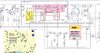
So the "tickler (R43 a 270K or so resistor)" places a steady voltage on the AGC sense input of IC1 - when the signals arrive, the S/RF meter pushes the needle upwards in scale - eventually the level gets past R44 and into the Diode/Resistor combo and summed in with power present the value R43 is chosen for - that tiny amount of "trickle charge" to start the fire - when the two sum together - the input Pin on IC1 "triggers" and starts to amplify that signal GREATLY - and this process ignites AGC into a control voltage to the RF Front End when signals arrive.

You'll see in the schematic of the Galaxy circuit - there is a Diode and Resistor "combo" placed in parallel to each other TOWARDS the input pin for AGC, but BEFORE the "tickler" from the Reference voltage - this lets the circuit use the diodes INTRINSIC ability to "avalanche into conduction" and make AGC act quickly to keep stronger RF signals from exceeding the "overhead" the designers built into the gain of the RF amp, IF strips and AF detectors - so they have enough room in signal level to work with, and add very little distortion - or at least less distortion than what could have happened if it had not been accounted for..

The Resistor (R274) part of this circuit gives the ability of the S/RF meters output - some Linearity, to handle flutter, fade and other aspects of signal degradation you may hear as you listen to distant stations. The diode is a one way valve - once it conducts - it's ALL IN - so it acts like a CLAMP to keep strong signals from overpowering the receiver and you also can hear both the weaker signals as well as the stronger ones within a similar volume LEVEL - so AGC does something to protect the amplifier stages, but also lets you hear weaker and stronger stations together within a specific range of volume level so your ears don't get too fatigued or your forced to ride the volume control excessively (Read: A LOT - you get tired of listening)

Resistor R274 can go DOWN in value - but this makes AGC stronger in reaction to wildy swinging radios - which may not work well for the listener. The value is pretty high, so it allows the weaker signals some ability to "swing" the needle - when you reduce the value of the Resistor - more power from the S/RF meter can get by the Diode and make AGC act more as a "Limiter" and "Regulator" - which can help in noisy traffic areas like cities and highway stops, but too much, everyone starts to sound the same and you lose your ability to hear the distant stations as "distant" versus the close-by stronger ones - can play tricks on your hearing. It can confuse you while you're driving - so careful with this resistor value.​

This AGC trickery and action only affects the NB indirectly - caused from the lack of "pushing back" the power of all the signals and noise embedded in all of that - so NB is more of a SECONDARY benefit of the AGC action - The NB can work harder but then - remember too - it is "inverting" the impulse noises it detects, so this may work AGAINST the lowering of the Nosie Floor and make the receiver even more noisy.

Ok, how do you fix that? You have other factors discussed in this thread to consider - one of them being the bandwidth of what you want to let in. So the Noise blanker is only going to do so much to REDUCE the initial noise you have in the signal "stream" arriving to the IF. - your NB is processing this in the 1st IF stream (or Strip)

So in your 1St IF, you have your Mixer, but before that, you have a PRE-SELECTOR - some call the Band Pass Filter or B.P.F. Some radios have 3 coil design, (HR2510) while others have just one or two (Galaxy L7 and L8). More coils can help "pare down" the bandwidth to help pull out your signal you want, but the price you pay is the LOSSES get quite high, to the extremely high losses when you arrive to the edges of the band (your bandwidth "skirt" losses are higher)

upload_2020-5-4_23-0-11.png
Galaxy uses a L6 (or L5) coil - open air coil - to help the RF amp in capturing signal. Roughly tuned to the band you want to receive - but you pay for it, the price is from this kind of open end capture is the noise level the signal may have around it is also getting amplified. So one signal you want, may get overpowered by another close by on another frequency that L6 allows thru - so this goes back to why AGC and PIN diodes are so important to have in these radios - to protect the receivr from those signals that would otherwise overpower and possibly damamge the receiver by strength of signal alone can overloand and induce distortion.​

The 1st IF has several coils much like the ones AFTER the RF amp but before the Mixer for your 1st IF. So one stage is working pretty hard as it is trying to push RF into being sorted out - but there are even more AFTERWARDS being used too - once you get the signal "bandwidth" range you want. So this extra filtering helps, but then DEGRADES the ability of the receiver to perform well in all conditions.

So, there are a lot of aspects to adjusting the RF front end of ANY receiver to accept these RX Mods - the effort comes from the laws of diminishing returns on your investment. DROI -

upload_2020-5-4_23-6-58.png

So, to put is simply, - if you have the time and the curiosity to try it, that's fine, but when you APPLY the mods, you need to take in many different variables into account, one being the Time invested, the AGC action you want to have in processing - and the limitations each design has; when you try to implement a mod that you have to figure out the requirements. Then apply those of the radio and the part and what they need to work together to accomplish what you want to have happen.

It does not always turn out the best for both the Radio, parts and even the Operator.
 
We find the ceramic AM filter in RCI-made radios frequently a kHz more more high, above 455 kHz. In a SSB radio with a frequency display, you're stuck with installing a filter that's on frequency.

But for the AM/FM radios with no frequency display, there's a workaround. Simply tune the PLL crystal trimmer coil to put the receiver dead on frequency. Now your transmit frequency will be off by a kilohertz and a half, or whatever the error was. But since these radios are just a SSB radio with no sideband, the transmit carrier frequency is adjustable. You set the 10. 695 trimmer coil to see the correct transmit frequency on an external counter.

This trick screws up the arithmetic that makes a frequency display accurate. But for the Connex 3300 and General Lee etc. folks, this will clear up the receiver audio once and for all. Besides, the driver will think you're a genius because the last few folks to look at the radio all just shrugged.

73
 

dxChat
Help Users
  • No one is chatting at the moment.
  • @ Wildcat27:
    Hello I have a old school 2950 receives great on all modes and transmits great on AM but no transmit on SSB. Does anyone have any idea?
  • @ ButtFuzz:
    Good evening from Sunny Salem! What’s shaking?
  • dxBot:
    63Sprint has left the room.
  • dxBot:
    kennyjames 0151 has left the room.