When you say you "check" - how or what are you using to do this? There's not a lot of places labeled TEST POINT on that board...
Did you see this?

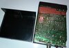
See Below...

The Xtal itself may work - but remember the Exciter is also trying to do something too. It's attempting to "ring" and start the loop feedback process.
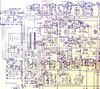
To start, look at the Blue Box section, the Xtal and there are two small caps, one is a trimmer cap to the right of the Xtal on the board (below green braid) and to the left of the Xtal is a square cap - these "trim" that crystal to a frequency close to 10.240 - but not exact - the CX trims to further fine tune it.
The Yellow Box shows two TANTALUM caps the PLL uses in a loop to two speeds - one high, the other low, they clock thru the PLL and as they "sync" together - this signal is a lot like a frequency. The PLL then determines this exciter and the divider inside itself if the channels are able to be tuned to - it uses the Exciter as the other half to check for "sync" and sends a error correction signal as part of this "Check gating for sync" process.
This is what made this radio unique, most of the other 5121 or 7132's used single cap designs for signal - ok I guess but was not the best smooth waveform the radio can use for IF processing - which the line sampled from that output of the Exciter - so if it was noisy - so went the IF...
Cobra even had a TSB for this...

Now, how do I know about that clock - is because if it doesn't lock in or find any frequency on any pin, it'll just keep the display blank - it's for the reason of servicing - to show something has failed internally.
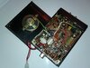
Did you check the Exciter coil - any "tampering" of the wax?

This thing is old, but there are spots on this board, that use older electrolytic caps that can dry out. That also can affect the signal you're trying to find. IF the coil is ok, but the parts have drifted off. That wax section will need some of the work you may have to "replace parts" done to it. That means removing as much wax physically before you start to reheat and remove/unsolder parts. The wax needs to be warmed, slightly, and removed so you can get at the parts, just don't apply too much heat at first so you can soften it then remove as much as you can in one piece.

So look into what I've listed above in a previous post - clean it up and reheat soldering joints in and around the VCO/Exciter section to see if you can get it to start oscillating (Ring). The Xtal itself may just need to be cleaned up or get the "glue" bonding it to the board/chip removed - so it can send more signal you can detect.
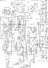
Something tells me that the Xtal may not be the problem but the caps used to "trim" and the dirt that the thing can collect around the glue can start siphoning off signal. See the schematic reference graphic above on the right.
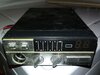
Considering the size of these things, they can be put just about anywhere in a small car onto a Chrysler Mini-van and were used like CB's onto even French Fry and Cup Holders.

So some can be abused and may not even work - it's the law of diminishing returns - you can only go so far before you have to give up on the cost or the effort or both.