Sunbulls, actually it was done with my iPhone. Maybe the lighting helped.Very high quality close-ups. May I ask what camera you're using? I need to get something a little better.

You are using an out of date browser. It may not display this or other websites correctly.
You should upgrade or use an alternative browser.
You should upgrade or use an alternative browser.
-
You can now help support WorldwideDX when you shop on Amazon at no additional cost to you! Simply follow this Shop on Amazon link first and a portion of any purchase is sent to WorldwideDX to help with site costs.
Cobra 29 wx st mod
- Thread starter Ocean cruiser
- Start date
Amazing the pic's phones take now . I have a cheap fairly decent Nikon Cool Pix but never remember to take it w/ me . For a fairly priced camera it takes great close up & Zooms in well . But if you don't have it with you ....... ?
For a fairly priced camera it takes great close up & Zooms in well . But if you don't have it with you ....... ? I'll post what I have to compare...

BTW - D18? That is for the sake of WX - your radio uses a "lockout" to keep Pin 3 from going into TX mode - so it keeps Pin 3 from keyup - that diode helps prevent the WX FORECAST from BLASTING THRU
Now, as you can see in my radios' version R101 is 2.2 ohm (Red - Red - Gold) while the R100 is a 2.7K ( Red - Violet - Red) BUT HAS NO DIODE.
D11? That's your Limiter - repair or ignore - that is your choice - but I'd look into fixing it, Put in a new 1N4148 and instead - See C73? Put is a Smaller value cap here - even a 103 Ceramic (brown body) Disc cap can work well here. Limiter will still function but not too tightly - you can also add a resistor on the foil side across C72, that gold-colored tantalum cap - to reduce the limiter clamping even more as needed - try 330 ohm ( Orange - Orange - Brown ) on up to 1K ( Brown - Black - Red )
It is my opinion that you can remove the Diode in R100 - anyone can run Hot Glue around there - and to me that doesn't look like it was an OEM fix. At least in my area of experience... You can replace R100 with the SAME value of 2.7K - you'll be fine.
L14? Sorry to see that, more than likely it's not replaceable easily - you'd have to scavenge one from another radio. They do work, just some take out the slug - there are mods in that section you can do - but it's a cap change - not a slug removal to make the L14 more effective - You change C60 from 472 to 471 (From 0.0047uF to 470pF - or less capacitance as needed to constrain slug to power effectiveness) to take away, or lessen that excessive capacitance - it removes the swamped capacitance the 472 (on the heavy side at that) that is presented on the C60 to L14 series circuit - Raising Xc - but you offset XL inductance to make it peak out better for the ORIGINAL 2078 in there. (Adjust L14 for this) You don't have the Slug so unless you can locate one - this mod may not help you.
See R55 - that 1 Watt 1K resistor? Not in the Graphic above, in your photo in your post of the main PCB. You can replace that with a 2.2K 1 - Watt or 4.7K 1/2 Watt - at least you'd have some way for static and noise to go to ground without pummeling the input Diodes and PIN diode sections.
Just some stuff to help you figure out that radio - good luck
Last edited:
Thank you, this is exactly what I needed. I’ll do my best.I'll post what I have to compare...
View attachment 33866
BTW - D18? That is for the sake of WX - your radio uses a "lockout" to keep Pin 3 from going into TX mode - so it keeps Pin 3 from keyup - that diode helps prevent the WX FORECAST from BLASTING THRU
Now, as you can see in my radios' version R101 is 2.2 ohm (Red - Red - Gold) while the R100 is a 2.7K ( Red - Violet - Red) BUT HAS NO DIODE.
D11? That's your Limiter - repair or ignore - that is your choice - but I'd look into fixing it, Put in a new 1N4148 and instead - See C73? Put is a Smaller value cap here - even a 103 Ceramic (brown body) Disc cap can work well here. Limiter will still function but not too tightly - you can also add a resistor on the foil side across C72, that gold-colored tantalum cap - to reduce the limiter clamping even more as needed - try 330 ohm ( Orange - Orange - Brown ) on up to 1K ( Brown - Black - Red )
It is my opinion that you can remove the Diode in R100 - anyone can run Hot Glue around there - and to me that doesn't look like it was an OEM fix. At least in my area of experience... You can replace R100 with the SAME value of 2.7K - you'll be fine.
L14? Sorry to see that, more than likely it's not replaceable easily - you'd have to scavenge one from another radio. They do work, just some take out the slug - there are mods in that section you can do - but it's a cap change - not a slug removal to make the L14 more effective - You change C60 from 472 to 471 (From 0.0047uF to 470pF - or less capacitance as needed to constrain slug to power effectiveness) to take away, or lessen that excessive capacitance - it removes the swamped capacitance the 472 (on the heavy side at that) that is presented on the C60 to L14 series circuit - Raising Xc - but you offset XL inductance to make it peak out better for the ORIGINAL 2078 in there. (Adjust L14 for this) You don't have the Slug so unless you can locate one - this mod may not help you.
See R55 - that 1 Watt 1K resistor? Not in the Graphic above, in your photo in your post of the main PCB. You can replace that with a 2.2K 1 - Watt or 4.7K 1/2 Watt - at least you'd have some way for static and noise to go to ground without pummeling the input Diodes and PIN diode sections.
Just some stuff to help you figure out that radio - good luck
Hi all, I know it's been awhile since anybody added to this thread but I was wondering since we are talking about mystery mods I would ask this question. I have a 29 ltd classic which was definitely hacked a bit before I found it. There is a resistor added in series with d17, which I believe is for the Delta Tune circuit and a resistor added in series with the modulation limiter (d11). Does anybody know what these two mods will do and should I leave them? Any help would be greatly appreciated.
Hack Mod LOL. Probably a mosfet final And they clipped every part that will make the radio sound crappy and squeeze a lot of meter watts that will just be harmonics.Hey gang, so I just got this cobra 29 wx st and noticed that it’s been peaked. Looking in the radio I seen this:
D11-cut
L14 slug- removed
R55-cut
R100- cut and a diode added.
Does anyone know what this mod is called and if there’s other parts That may have been change, added or removed. Thanks
Lol..yes definitely hacked. They removed l14 and l16 slug. Mosfet swing kit, yaddah yaddah. I've seen those mods done before. However the mod limiter, d11 is not clipped but instead a it was lifted from the board and a resistor was put in series. The same was done for the d17 delta tune diode. The effect those two things would have is what I'm wondering.
Andy could probably figure what the delta tune hack does. I am thinking the resistor and diode on D11 is a copy of a galaxy swing mod but I would love to see it on a scope. Possibly I will try it on a 29 and look at before and after on a scope. What size resistor or can you post a Pic?
Unless I can see HOW they put the resistor in, Across - Series with, or over - there are different "Responses" to each one.
Not to say it's a good mod, but you're right, they definitely are a different mod.
One way, you're in the "dimes" other way your "touchy" and another just drifts with temperature.
Not to say it's a good mod, but you're right, they definitely are a different mod.
One way, you're in the "dimes" other way your "touchy" and another just drifts with temperature.
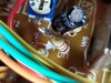
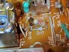
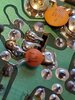
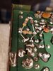
Hi Andy, thanks for hopping in here. Here are the pics from the mods in question. The first two show the two spots where resistors where put in series for d11 and d17. It's an 8.2k resistor on d17 and a 1k resistor on d11. The next two photos are showing a couple of other things that I noticed that were done, a 100pf cap was added on the backside of the board tying in parallel to c62 and a very strange looking companion part for the Mosfet upgrade. If you can shed any light on what these are doing and if they should go or stay it would be very helpful. Thanks again!!
Attachments
Here's the easy ones...


The Mods shown are Furnished for Educational Purposes Only
Attempts to Modify Radio Equipment or Performing work like these Mods suggest
can violate warranty and FCC Type-Certification.
End User assumes All Responsibility.
The Mods shown are Furnished for Educational Purposes Only
Attempts to Modify Radio Equipment or Performing work like these Mods suggest
can violate warranty and FCC Type-Certification.
End User assumes All Responsibility.
There is one small problem with the last pic, the MOSFET mod...
This looks like it was "Tacked in" and they wouldn't be able to use the radio when they tried to put the covers back on, it would short out. So the last one is obviously showing something's up. It needs considerable amount of detail that you need to show the top component side of the board - so if you "flip" this over, you would damage the components shown - so what are you trying to do?
So you are showing mods, but are you using this for training purposes?
So that explains why I seem to have to keep my delta tune all the way to the left for clear recieve. I think I will eliminate that mod as it seems like more of a nuisance than a benefit. The companion part was heat shrunk and gently folded flat so it does not short on the cover. I just exposed it for purposes of the photo and I know that some guys selling Mosfet kits include a companion part which installs in that location, such as bigdawgamp's kit on fleabay. I just never saw that particular arrangement of diode/resistors before and was curious as to what this would exactly do. Just bias for the final? So the 100pf cap at C166 caps power output of the Mosfet? Not sure why anybody would want to do that since the whole point of converting to a Mosfet is for increased output...at least that is my understanding. Yes this is kind of a training and learning radio for me. I'm totally new at working on radio's but do have some limited knowledge of basic electronics and I find all this very fascinating. I can't thank you enough for all the great information and time that you put into this forum Andy, as well as the patience to deal with newbie rookies such as myself.
Well to only go over the mods...
I saved that last one because for what ?I? may fear is for some one or some entity to come along and in light of the "yahoo security breach" - posing as an "Actor" only to obtain information the members offer - and take it to eBay or worse - and we all wind up getting "Blacklisted" because of the "Things we know - We know too much"
I have been taken to the "Cleaners" before and as a former member of another site - the Moderator/Owner/Creator of it as well as many others - their data was compromised - and it never goes well afterwards.
So - 3 out of 4 CB'ers prefer mods that work...
The last one I usually do as a two-sided approach.
It dates back to the time when that site was still functioning...and due to the nature of the Mod itself - I only provided Graphical drawing support for that user. The Mod was going into a Cobra 19 LTD/GTL using the 9109 PLL.
Still used the 2078/2075 BJT platform but we swapped it out and had to figure out layout and parts needs to make the conversion work, but it was modded for other reasons - mostly due to family. So due to the nature of the beast, Covid 19 and out of consideration for the User that I worked with, I can only say that those values are approximate and depend upon how large the C62/C166 values are used.
But the small changes in RF presence - capacitors can help with that - you have to overcome the "Steady State DC voltage" that static presence and make the MOSFET follow the Gates' lead and operate somewhat linearly. You'll see it was one of the BJT's major selling points, Analog linearity versus a non-linear and Digital switch taking it's place. But BOTH only need small amounts of change in power to make larger swings in power at their output.
With these mods, comes a responsibility to use them. Although the days of Analog TV are behind us, you still can cause tremendous amounts of damage to a neighborhood if the knowledge is not used properly - and you may have to face the music because of it.
I saved that last one because for what ?I? may fear is for some one or some entity to come along and in light of the "yahoo security breach" - posing as an "Actor" only to obtain information the members offer - and take it to eBay or worse - and we all wind up getting "Blacklisted" because of the "Things we know - We know too much"
I have been taken to the "Cleaners" before and as a former member of another site - the Moderator/Owner/Creator of it as well as many others - their data was compromised - and it never goes well afterwards.
So - 3 out of 4 CB'ers prefer mods that work...
The last one I usually do as a two-sided approach.
It dates back to the time when that site was still functioning...and due to the nature of the Mod itself - I only provided Graphical drawing support for that user. The Mod was going into a Cobra 19 LTD/GTL using the 9109 PLL.
Still used the 2078/2075 BJT platform but we swapped it out and had to figure out layout and parts needs to make the conversion work, but it was modded for other reasons - mostly due to family. So due to the nature of the beast, Covid 19 and out of consideration for the User that I worked with, I can only say that those values are approximate and depend upon how large the C62/C166 values are used.
Until he can return to this site and offer - I do not want to overstep my bounds and generate even more bad karma. So I won't publish the data without their knowledge and or consent.
What I can tell you is what was learned from it -
What I can tell you is what was learned from it -
- The 100pF (101)? That part is piggy-backed with the original cap - a 220pF giving you ~320pF to offset the INPUT capacitance the MOSFET needs. That's is why this mod is what it is, it can be quite intricate and detailed in implementing. And not everyone likes the results let alone the "fiddling" of values to make it work right.

- Again, you have to know the parts and requirements the Driver and Final needs to perform - for if you use too large of a value of capacitance - they "latch-up" and burn out because they aren't producing RF they're just "On" due to the FET response nature these devices have. A lot like a Latch.
- They aren't Bi-polars (BJT's) which require some form of power to turn on, in both Voltage and Current (more current than voltage) to conduct - MOSFET's require nearly ZERO current but a good steady Voltage in which to work. BJT's Designs' use what I would call, continuous form electron flow junctions - the entire device is one solid conductive piece of sand-grains - so the junctions "touch physically and electrically together" and so their properties are of a continuous substrate nature.
- MOSFET's are not the same when it comes to continuous flow - for the Gate is INSULATED from the substrate below it - so RF doesn't - Electrons don't - Propagate thru the device as a continuous intrinsic piece of a semiconductor.
- RF works differently in the BJT than any FET or MOSFET device. Transistors are a lot like Diodes and they exhibit an INTRINSIC impedance to changes in both Voltage and Current that MOSFETs' don't.
- MOSFET's also have junction's like a typical Planar (PN) semiconductor just made differently - but act a lot like tube grids - ready to control large volumes of power thru the Cathodes to Plates.
- HOWEVER, They have insulated Gates - and only need a voltage to "Fire"
- - BJT's are different they need current behind that voltage to "fire" so they (Designers) developed biasing techniques and refined them
- MOSFET can take these small RF signals to the next level and "fire" by simply receiving RF that they can RECTIFY thru their Gate structure. It means they can go into self oscillation and burn out from this trait. The "Voltage" presence helps the Gate in determining RF is present or to stay off. A biasing support issue. Having a pure clean voltage prevents the Gate from sensing any stray RF or other ambient capacitive influences - Read as: Voltage Spikes. and incidentally turn on - Destroying the device and all your work in the process.
But the small changes in RF presence - capacitors can help with that - you have to overcome the "Steady State DC voltage" that static presence and make the MOSFET follow the Gates' lead and operate somewhat linearly. You'll see it was one of the BJT's major selling points, Analog linearity versus a non-linear and Digital switch taking it's place. But BOTH only need small amounts of change in power to make larger swings in power at their output.
With these mods, comes a responsibility to use them. Although the days of Analog TV are behind us, you still can cause tremendous amounts of damage to a neighborhood if the knowledge is not used properly - and you may have to face the music because of it.
Last edited: