• You can now help support WorldwideDX when you shop on Amazon at no additional cost to you! Simply follow this Shop on Amazon link first and a portion of any purchase is sent to WorldwideDX to help with site costs.

cobra 2000 receiving and tx but channel not changing.

MB3756 Outine

upload_2020-2-13_7-56-57.png
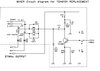
Well, if I read your Regulator references to voltage - your regulator seems to be shot. All voltages appear on all the TOGGLED lines the CONTROL line is supposed to do it for you.

Input Pin 2 ok, as well as Ground Pin 4 - should be what they are supposed to be, but Pin 3 remains active ALL THE TIME - Pins 8, 6 change states when you Key and Unkey the mike.

So, that raises another question - do you have the Mic handset wired correctly for it?

To see TX on all the time, PREVENTS you from changing to any other channel - so we may have an answer there.

Check to see if you have shorts or more bad caps along the lines that go to the MB3756...
 
Old T , :ROFLMAO: Actually I'm getting ready to start some havoc W/ a few locals ! I don't mind op's having a few Beers & Chatting , but these 2 have Vodkaitus ! They don't shut up till I key up ! Just trying to keep my local channel under control ! These 2 are about 35 mile in opposite directions . Thankfully I'm on my A-99 & believe me 650 is nothing for me ! Still have a few in reserve . :whistle: If I need help I give my buddy a LL , he good for 5K ! He's has a shell fish license also .:LOL:
 
What a local channel I have ( In RI ) ! It's called Big Radio Boulevard , stop by 21 am some time when Dx is in , Give 357Magnum a shout ! :) We also have a FB Page for BRB if your interested . 73 & God Bless , Leo
 
The PLL chip's out-of-lock detector probably has a string of pulses riding on it. C135 serves to smooth out these pulses to a steady DC voltage. That steady DC voltage is what shuts down the receiver audio. The pulses alone can't do that as well, causing the receiver audio to increase when C135 is unhooked..

This symptom tells us the PLL is having a hard time maintaining its grip on the channel frequency, but isn't completely disabled. Sometimes called a "marginal lock".


A common cause for instability like this is for the tuning slug in L21 to be set wrong. This will reduce the signal level that feeds into pin 17 of the 8719 PLL chip and cause it's "lock" to be erratic.

Since there is no change in either receiver or transmitter level when the slug in L21 is turned, a "tweaknician" may just turn it randomly, and move on the next adjustment when he sees no change up or down from turning it.

A 'scope on the spot where the + side of C135 would be connected will reveal this string of pulses. This is the only way to get L21 adjusted. Can't use the receiver S-meter or the wattmeter to peak it properly.

If you can put a 'scope onto pin 17 of the PLL chip, peak the slug of L21 for max signal level. If the level at pin 17 is seen to increase in a significant way, this should fix the issue with losing receiver audio when C135 is connected.

73
 
Took me a few minutes to find C135 on the schemo.

Just an educated guess, but I think this is what he's seeing.

Probably should have pointed out the potential hazard of a bad capacitor inside L21, causing the slug to 'peak' with the top of the slug dead-even with the rim of the hole.

When you see this, it's not really a peak. Just behaves that way at this slug position. I'll skip the explanation why, and what to do about it until I hear if L21 adjusts properly, showing a peak with the slug at least a couple of full turns below the rim of the hole.

73
 
  • Like
Reactions: 357magnum
good morning and thank you all for the help.
so i have replaced the voltage regulator regulator and the new voltages are
pin 1.......... 8.3
pin2 ......... 13.5
pin 3 ....... 8.3
pin 4 ...... 0.0
pin 5 .... 13.5
pin 6 .. ... 8.8
pin 7 ..... 0.00
pin8.. .5

Now i can still hear static in the speakers and tx/rx is not switching.
I have checked over the microphone wiring its fine, i have checked it in another radio also.
I have put the scope on pin 17 of the pll and i dont see anything on trace......
i also checked the 10.240 with the scope and its fine.
is there anything i can check to ensure the pll is working

i just checking out voltages at tr20 they dont appear correct collector 4.8 base is 2.9 emitter 3.7.

jim
 
Last edited:
If there is no signal on pin 17 you have found the problem.

Or the tail end of it, at least.

What should be there is a difference frequency under 2 MHz. Comes from mixing the 3rd harmonic of the 11.325 crystal, coming out of L21 with the 35 MHz ( plus or minus) VCO frequency.

If either of those two input frequencies shuts down, or if the mixer they feed into quits, you'll have no signal at pin 17.

Next question is where did the parade stop? At L21? At the 11.325 crystal feeding into L21? At the VCO?, Or the mixer transistor those two feed into?

Somewhere upstream from pin 17.

73
 
Thanks nomadradio
That's great information
So I will try to investigate that area
I will try to find if 11 3258 is working for a start.
Your explanation of how it works really clarifies what I need to do next.
I will send on the results.
For information like you just gave there, would lou Franklin's book book understanding cb.....be the one to have as I have few other CBS here including the old versions of the McKinley before and with the fm. Just looking at the boards they appear fairly similiar to the cobra.
Anyway that's another day
Thank you.
 
Ok so far if checked tr 20 it has emitter 33.975
Collector variable and base 35.475 mhz

And tr29 emitter can't measure anything
Collector 33.975 and base 11.325
...
 
Here's something to help you...
MB8719Cobra2000vs148GTL.jpg

Pin 17 on the PLL as Nomad pointed out, takes in a DIFFERENCE signal...it is what the "gated" stuff just on the OPPOSITE side of the chip does and there is an output correction signal sent to the oscillator from the Chip to speed up or slow down the speed of the oscillator using the Varactor to adjust this voltage to a tuning capacitance.

If the speed is too great the Charge Pump raises it's voltage - opposite is true if it's too slow...

How does it know?

It uses the output of TP10, that boxed portion is used as a LOW-PASS filter to circulate the low-frequency signal back to pin 17 and keep the loop oscillator working in the +30MH'z range without dragging it down.

That low-pass filter takes the mixing products' low-frequency side - as a fundamental of frequency mixing - called Heterodyne...

Heterodyne.gif
 
Thanks Andy,
i have checked all the vco voltages and they appear right to whats in the schematic except for pin 10 thats only 2.01 and pin 5 is 6.9 v

i have checked tr 20 out of circuit and it also is ok but the voltages at its collector are only 4.8 and 4.03 at the base.
i have checked r207 and its ok.
Do you think the problem is in the low pass filter perhaps capacitor c87 c88 c89 r101.
many thanks again
jimmy
 
Last edited:
Might be an issue with UHIC 007 - that may have a failed part. The pin is output for the internal Varactor.

Doesn't normally go bad though...

I'll have to defer to Nomads opinion first...
 

Attachments

  • TDA6131Mixer.jpg
    TDA6131Mixer.jpg
    107.3 KB · Views: 5

dxChat
Help Users
  • No one is chatting at the moment.
  • @ Wildcat27:
    Hello I have a old school 2950 receives great on all modes and transmits great on AM but no transmit on SSB. Does anyone have any idea?
  • @ ButtFuzz:
    Good evening from Sunny Salem! What’s shaking?
  • dxBot:
    63Sprint has left the room.
  • dxBot:
    kennyjames 0151 has left the room.