• You can now help support WorldwideDX when you shop on Amazon at no additional cost to you! Simply follow this Shop on Amazon link first and a portion of any purchase is sent to WorldwideDX to help with site costs.

Part 2 SR-955 AT 6666 Audio expansion worked out and now public

711

Well-Known Member
Mar 22, 2008
340
398
73
I’m sorry the OP deleted his thread. I dislike putting energy into a post on the open forum to have it deleted due to feelings? Anyhow, like all post here , for the benefit of helping everyone here . This is the original post
From the OP

After Working with a very smart member of the community we figured out the Audio expansion for these 2 radios.

We will release to the public more radios as we figure out and test them.

We are doing this as a public service to the whole community because of one shop that thinks he is the only place on earth that can figure this stuff out. (Tap Tap pay attention)

** Note you need to be able to de solder and re solder 0603 components.... If you can not accomplish this then send the radios to a tech that can

for the 955 you will need
2 0603 in the following values
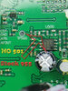
1-180PF
1-100K

For the AT6666 you will need
2 0603
1-100K
1-200PF

What does this do??
Well a stock 955 and at 6666 average audio is about 200MHZ to 3100KHZ..
Our parts changes will let your radios work from
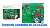
about 100MHZ to 41-4200KHZ
So again this does what?
Well it expands the audio tones that can now be sent out of the radio
IF IF IF IF IF IF your voice hits these higher or lower tones then people will hear your SSES TEEZZ and PEEZZZ a lot more pronounced and sharper.
It can and does on the 955 enhance the stock mic quality as well.

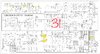
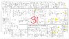
Image attached with locations of components and changes to be made..
Enjoy and If you liked this mod please leave a comment below..
 

Attachments

  • C1B828BD-8828-41BE-9103-A8CCE5C4C81A.jpeg
    C1B828BD-8828-41BE-9103-A8CCE5C4C81A.jpeg
    461.4 KB · Views: 70

My original reply was that I had posted the Lincoln 2 mods for it which share the same board. I also wasn’t the first to figure it out not only one lol
 

Attachments

  • 6910C0B1-D090-471A-9E62-8048568FD166.jpeg
    6910C0B1-D090-471A-9E62-8048568FD166.jpeg
    765.7 KB · Views: 31
  • E668FDEB-BE0C-4959-8D4C-9D7222934C70.jpeg
    E668FDEB-BE0C-4959-8D4C-9D7222934C70.jpeg
    714.7 KB · Views: 25
And then there was me...
I'll try to give a little history...

upload_2020-3-22_17-0-56.png

And they repeated themselves...

So to cut to the chase - we were talking about this...
upload_2020-3-22_16-56-47.png

And also wanted to point out to them that 100mhz - I think they meant 100Hz (Bass to Alto Range of voice)
and to keep people from using the WRONG decimal point 4,100kHz equates to about 4.1MHz - so I only corrected them to a certain degree...4.1kHz - looks better
 
I feel like the mic preamp and forward stages has a lot of gain and audio shaping built in. From mild to wild a lot can be done on these chassis albeit on the SMD level
 
  • Like
Reactions: AudioShockwav
Be sure to put it in here...

Thank you.

Yes, but on my other location PC. Will edit that post tomorrow with proper content.
Mike

To be honest - they were trying to post an article - that at the moment will remain out of the scope of this series because the work was AUTHORED by someone else - how the OP acquired this information was none of my business but to find the article was thru a dialogue from someone pestering someone else - the issue of a filtering process came up...

So Instead of going down the wrong "grumbly" path, I wanted to post this graphic for others to see - this information was available but since I was "not asked" by those that "Tap - Tap". They kept me out of the loop for in hindsight would have helped their efforts if someone PROOFREAD their work before they posted the graphic you see above... - I got some Better answers as to how the last U500 - that 4558 Chip is used...

Graphic below is the 955 Audio Amp strip, including the Mod limiters, and the branches the MOD; once processed - was sent to the section of the radio to be amplified - this is on a Stryker - but I will also CAUTION you - they do similar work on other radios like the AT-6666 - so this is a LEGACY as well as Evolution - process...
Stryker955AudioMods.jpg
The Blue Circled item is what THEY removed - per their sheet - not mentioned original postings but I think when it was mentioned this way - they got scared...on top of the Red - which they REMOVED C543 Changed C542 (180pF) the also removed that Ripple Filter C501.

What they are doing is removing a cap in the filter network - this claim is for those that may not notice the differences - but if you are into Hi -Fi - you certainly will hear it as a low-rumbling rattle sound added to your voice - and they called this opening up the audio...

The U500 - the twin amp feature is a filter to sharpen the voice products picked up by your microphone and best idealized per-se for the Stryker radio to use and amplify in the various stages...

It's called Sallen-Key - in reference to Topology; is used for defining a circuit used within another circuit - like you're adding a map to make the circuit perform a function and calling it a process...


As you look above at U500 - that filter network uses two capacitors along with a 3-rd not deemed used in the Wiki version of the filter
  • - but it is used heavily in other CB radios as a Ripple or otherwise offset fitler to remove eddy current and phase effects when audio - being an AC signal - is amplified in single ended power supplies.
  • In the application with the Stryker radio - it can be considered a smoothing filter that lends to have a low-end roll off - so when the cap is removed, the Unity gain of the amplifier is kept, but a means to tighten the Bass response was removed.

The other aspect the article Tap-Tap - stated was the use of smaller capacitance - that in itself can increase the Bandwidth of the device and not have to require removal of so many parts.

So they DECREASED the Capacitance in two locations and needed to change a Resistor from 220K (the 224 in the photos) to 100K
  • - the removal of capacitance affects the overall headroom the amplifier has to work with
  • - it can easily OVERAMPLIFY and distort
  • - in using the Feedback filter stage like this - you are taking a unity gain amplifier and making it more of an attenuator
  • - so we have to be careful with how much is taken out so something else has to be also reduced to maintain that unity
  • ...remember were trying to improve bandwidth.

So what does this have to do with the HR2510 - or the HTX article from SP5IT? Quite a lot - for we overdo things when we take a part out thinking we will get more. Oh - yes we do, at a price. (You know - I never would have believed I would be saying that right now...but it has to for the hobby and Radio itself is to survive it has to be practiced.)

The better method is to locate the Resistor that Sources the signal into the amplifier - note it is a 220K - that 224 in the above picture of the board. You have two caps filtering - one is a Ripple - leave that one alone for the broad banding addition part we are going to put ACROSS the pads that part was removed...you put in a value larger than the 220K - and this is up to you - I would use 390K ~ 470K as the values to offset the gain the 220K injects into the gain loop of the filter. You are paralleling a part that then divides power between the two parts instead of a single one.

So at the Red Dot - Keep the cap - you can straddle a 390K (394) on up to 470K (474) chip resistor on those two open pads or across the top of the cap still there at location C542. This will improve the bandwidth better and provide a method to attain Unity of this follower amplifier being used as a filter. At least you have better sounding voice out of the Mics' or whatever you use - with less distortion.
 
Isn’t it kinda hard to impossible to remove something that was never there to start with? Speaking about C543 and C501, they aren’t in the 955 from the factory.
 
Goldfinger has these mods on wwpdx:


TX all modes:
Change C534, C571, C570 to 1uF or 2.2uF non polarized
C530 is already 1uF.
AM: Change C527, C153, C152 to 1uF or 2.2uF non polarized. Change E14 to 330uF 25 volt or higher Electrolytic, observe polarity.
FM: Change C528. C536 to 1uF or 2.2uF non polarized
SSB: C528. C539 are already 1uF

Direct inject at C152


The echo board will likely have to be bypassed for these mods to work completely.
Edit: The echo board looks like it has all 1uF caps in the audio chain except C900 which is a .1uF Changing it to a 1uF will fatten up the lows some. Bypassing the echo will still be better for full audio bandwidth.


RX all modes:
Change C136, C137, C165 to 1uF or 2.2uF non polarized
Change E10 to a 1000uF 25 volt or higher Electrolytic, observe polarity.
More highs: Make C37 lower in value
AM: change C163 to 1uF or 2.2uF non polarized
FM: Change C135 to 1uF or 2.2uF non polarized
SSB: Change C197 to 1uF or 2.2uF non polarized

wwpdx
wwpdx.com


What are the smallest/lightest caps for the replacements that don't call for E caps I could use here? I'm thinking trim & bend the leads to be short where I can put a bit of glue/cement to hold the cap down to the board once it's soldered to the existing SMT part.

https://www.mouser.com/ProductDetail/Pa ... Qg6bFXA%3D

wwpdx
wwpdx.com
 
Last edited:
  • Like
Reactions: AudioShockwav
Isn’t it kinda hard to impossible to remove something that was never there to start with? Speaking about C543 and C501, they aren’t in the 955 from the factory.

Please Read this...

http://www.areciboinstruments.com/Qixiang.aspx

He updates as he goes, and today...he's not happy...

But thanks for the update...I now know something more about the Stryker - I never had one to mess with that area but I now know those values are used schematically...

So there is more to this - and it's dynamic...

The conversation this ting generated is wonderful!
 
Actually he doesn’t update as he goes, that was posted days ago and I wouldn’t be happy either if I was him. That is NOT the original poster, that is NOT DaveW, there’s some confusion here. If I was getting trolled and flames over someone’s mistake, I wouldn’t be happy either.

And look at it like this, that was is much simpler and easy for the novice guy to do, the goldfinger stuff is more drawn out. Remember the size of the components we’re talking about here...
 
@TheRealPorkchop - Glad you're out here, kinda' wondered where you've been...were you out Galaxy-ing - checking out the new stuff, new dives, divas, Showing off the stuff the Force is made of...?
upload_2020-3-23_7-10-44.png

But on a lighter note...

The issue of the "Missing parts" - I was trying to make a point of ...
  • If you are, already missing, these filter elements,
  • Why are you taking out even more...?
I'm also concerned about the Plagiarism issue - for the top of his page shows 3/22 - being just yesterday at the website. So if they're mad, this isn't over...

Since the thread was deleted, I could only grab so much but this is EARLY SUNDAY Morning screen shot of his website shown in the link above...
 

Attachments

  • AudioBandwidthA666Str95S.png
    AudioBandwidthA666Str95S.png
    932.8 KB · Views: 36
Be sure to put it in here...
- which they REMOVED C543 Changed C542 (180pF) the also removed that Ripple Filter C501.

.

Well you best ask Stryker then as 501 is not there on a STOCK stryker it was not removed at all by anyone.. it is not there stock!!
Do you even have a 955? open it and look it is Not present
you have stared your useless tearing apart of a simple expansion without even having a 955 in front of you, this is why I deleted my post you have zero clue what the heck you are even doing..
 

Attachments

  • 955555555.jpg
    955555555.jpg
    533.7 KB · Views: 22
  • Like
Reactions: TheRealPorkchop

dxChat
Help Users
  • No one is chatting at the moment.
  • @ Wildcat27:
    Hello I have a old school 2950 receives great on all modes and transmits great on AM but no transmit on SSB. Does anyone have any idea?
  • @ ButtFuzz:
    Good evening from Sunny Salem! What’s shaking?