
You are using an out of date browser. It may not display this or other websites correctly.
You should upgrade or use an alternative browser.
You should upgrade or use an alternative browser.
-
You can now help support WorldwideDX when you shop on Amazon at no additional cost to you! Simply follow this Shop on Amazon link first and a portion of any purchase is sent to WorldwideDX to help with site costs.
meanwhile out in the garage ...
- Thread starter kopcicle
- Start date
1982 kawasaki KZ1000 CSR
998cc transverse inline 4 cylinder
70 x 66mm bore and stroke
two valves per cylinder , dual overhead cams
HP/Torque is nearly "square" @ 100
It's a bit of a blunt instrument in a razor edge world.
Kinda like , what do you want, a modern fuel infected LS6 or a 70's era 427 Mk IV big block with dual 4 barrels?
True there are some liter bikes today that are pushing close to 200HP @ half the weight but the brutality and low end torque of the Kawasaki "J" engine still has some appeal .
Then again I Have a plethora of parts for this engine including several top ends with displacement up to 1260 and cylinder heads to match.
Does it get modified or swapped into the cop chassis or flipped or turned into a fire breathing beast remains to be seen .
I have yet to get it off the truck
")
A good friend of mine had a 1980 KZ1000 with the 1015cc variant of the 1000 engine. He owned that bike until his death in November when it was passed to his oldest son (who doesn't ride, but that's for a different story).
I was allowed to ride that bike many times when I would trek back to Illinois to visit and we'd go for rides with some other friends.
I have always owned Hondas, but I have a special place in my soul for this era KZ.
I was allowed to ride that bike many times when I would trek back to Illinois to visit and we'd go for rides with some other friends.
I have always owned Hondas, but I have a special place in my soul for this era KZ.
http://www.bunkerofdoom.com/lit/4x8/index.html
The 4x8 Power Supply
This article describes a simple power supply which provides two voltages, one which is twice the value of the other, and uses full wave rectification and doubling without a center tap on the power transformer. This is one alternative to the popular "Economy" power supply.
First, the "Economy" power supply is described in order to illuminate the points of its operation, and then the "4x8" design is described.
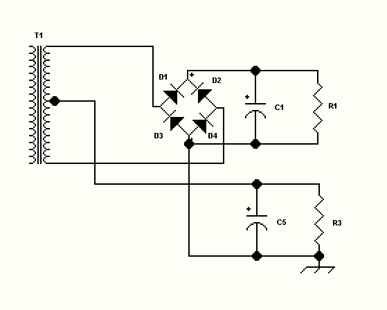
Figure 1. Economy power supply
The "ecomony" power supply shown in figure 1 has long been used where two voltages are desired from one center-tapped transformer. In accordance with the nickname "Economy", the purpose is to use only one transformer, saving cost, weight, space, and a few parts such as rectifiers and protection devices which would be needed if a separate transformer and rectifier system were used for the additional output voltage. The most common application is for vacuum-tube technology, where, for instance 800 volts is needed for the output tube's anode supply, and a lower voltage is needed for the rest of the circuitry (oscillators, preamplifiers, drivers etc). The low voltage output of the economy power supply produces half the voltage of the high voltage output. An analysis of the curcuit shows that the high voltage is derived from bridge rectification of the voltage across the entire transformer secondary and accumulated across C1, while the low voltage is derived from the center tap, and rectified by diodes D3 and D4 and accumulated across C5. The resistors in the schematics represent the loads. In the economy power supply, the high voltage load draws from the entire secondary at all times, and the low voltage load draws from only half the secondary at a time (each half-cycle it switches sides).
The "4x8" power supply does not need a center tap on the power transformer, and for the same output voltage and power as the economy supply, requires a secondary with half the voltage and twice the current rating as the economy supply. This is niether an advantage nor disadvantage, but the "economy" and "4x8" designs compliment each other by allowing greater flexibility in the use of existing transformers.
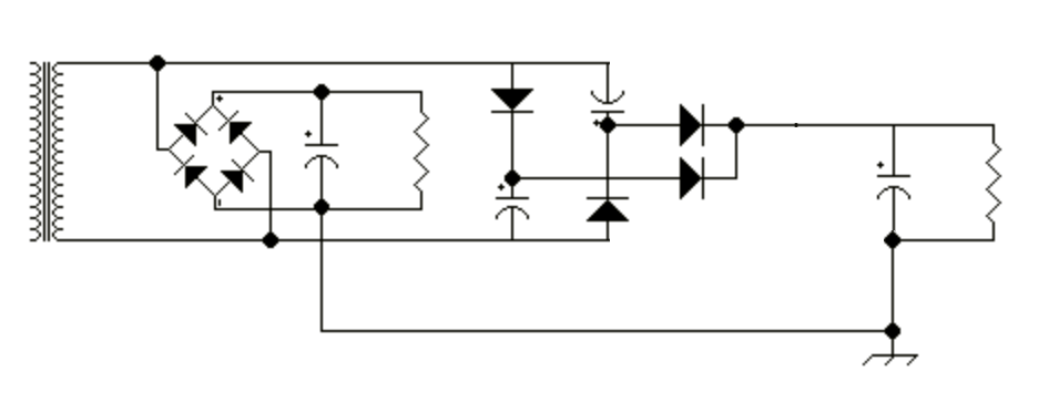
Figure 2. 4x8 power supply
The 4x8 power supply in Figure 2 uses eight diodes and is a combination of a bridge rectifier and a pair of voltage doubling stages. Using two doublers enables the full multiplication to occur every half-cycle, rather than only once per cycle as with most other multipliers.
To envision the working of the doubler circuit, figure 3 below shows the power supply built of a separate low voltage section composed of a full bridge rectifier composed of D1 through D4 and C1, and a separate voltage doubler, composed of D5 through D10 and C2 through C4. In the actual version, the functions of D7 and D8 are performed by D3 and D4 of the bridge rectifier respectively, and D7 and D8 are deleted.
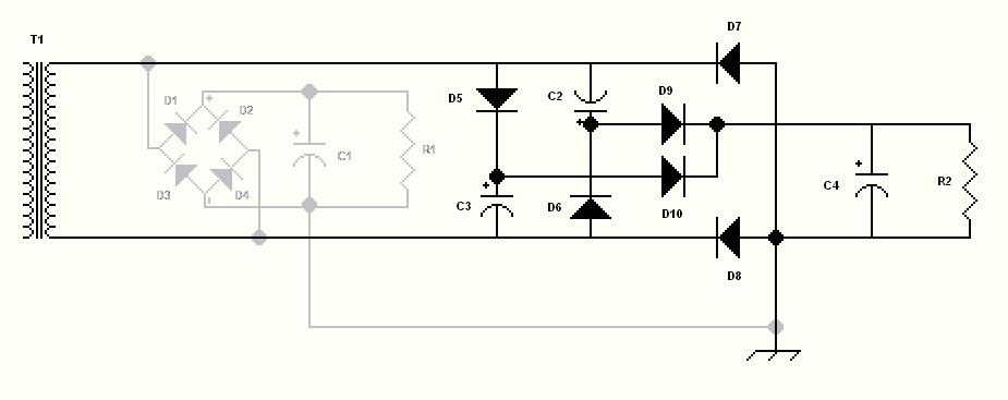
Figure 3 How the doubler works
The bridge rectifier section is familiar and needs no explanation. For now, just pretend it does not exist. The voltage doubler requires five half-cycles (two and a half cycles) to enter a steady-state mode of operation. It works as follows:
During the first half-cycle, the top side of T1 is positive. C3 is charged through D5, and C4 is charged through the series connection of D5 and D10.
During the second half-cycle, the bottom side of T1 is positive. C2 is charged through D6 and C4 is charged through the series connection of D6 and D9. Therefore C2 and C3 are charged on alternating half-cycles, and C4 is charged on every half-cycle.
This brings the system to the point where one complete cycle has passed and C2 through C4 have each been charged to the peak voltage available from the transformer. During the second full cycle of voltage and thereafter, C2 and C3 having been charged, the doubling action is performed.
During the third half-cycle, the top of T1 is positive. The charge on C2 is in series with the positive voltage from T1. The charge on C2 reverse-biases D10 and C2 is discharged into C4, raising its voltage to twice the peak voltage.
During the fourth half-cycle, the bottom of T1 is positive. The charge on C3 is in series with the positive voltage from T1. The charge on C3 reverse-biases D9 and C3 is discharged into C4, raising its voltage to twice the peak voltage. C2 is recharged through D6 during this time.
During the fifth half-cycle, the top of T1 is positive. The charge on C2 is in series with the positive voltage from T1. The charge on C2 reverse-biases D10 and C2 is discharged into C4, raising its voltage to twice the peak voltage. C3 is recharged through D5 during this time.
The power supply is now operating in a steady-state mode, with the events of half-cycles four and five repeating until the AC input is removed.
A test case, using the PSUDII simulation tool, shows the outputs of the power supply. In the usual radio communications circuits, the low voltage section delivers only 1/4 to 1/3 of the current which the high voltage section is called upon to supply (most of the current is used at high voltage in the RF power amplifier circuit). PSUDII can only simulate one rectifier section at a time. In order to obtain accurate results from PSUDII, it was expedient to have the same current drawn by each rectifier section. To account for transformer losses due to the current being drawn by the section not being simulated, the impedance of the transformer (I2R loss) was doubled in the simulation.
Parameters for the Economy supply (Figure 1)
Primary voltage = 120VAC 60Hz
Secondary Voltage = 600VAC with center tap at 300V.
Primary DCR = 0.1 ohm
Secondary DCR = 100 ohms
Transformer Impedance = 104.4 ohms
D1 through D4 = two 1N4007 in series
C1 = 220uF, resistance = 2 ohms
R1 (HV) = 4000 ohms
C5 = 440uF, resistance = 1 ohm
R3 (LV) = 2000 ohms
Parameters for the 4x8 supply (Figure 3)
Primary voltage = 120VAC 60Hz
Secondary Voltage = 300VAC.
Primary DCR = 0.1 ohm
Secondary DCR = 50 ohms
Transformer Impedance = 50.6 ohms
D1 through D4 = two 1N4007 in series
C2, C3 = 440uF, resistance = 1 ohms
R1 (LV) = 2000 ohms
C4 = 440uF, resistance = 1 ohm
R2 (HV) = 4000 ohms
Note: tabulated values are RMS unless otherwise stated.
Topology peak transformer
secondary
current D1, D2 peak current D3, D4 peak current HV load voltage HV ripple
peak to peak HV load current LV load voltage LV ripple
peak to peak LV load current
Economy 1406mA 701mA 1406mA 703V 4.8V 176mA 352V 2.4V 176mA
4x8 1735mA 705mA 1735mA 634V 1.16V 159mA 352V 2.4V 176mA
As can be seen, the 4x8 design can provide about the same voltages as the economy design. The slightly lower output values for the 4x8 are mostly due to higher peak currents and resultant I2R transformer losses caused by the voltage doubler's high peak current requirements.
In the economy circuit, the transformer secondary current averages out to about 3/4 of the value found in the 4x8 circuit. This is because the economy circuit draws power from the entire secondary for the HV output and only half the secondary for the LV output during each half-cycle, contrasted with the 4x8 which draws power from the entire secondary for both outputs every half-cycle.
This is why it is important to use a transformer with winding resistances which are as low as possible when using voltage doublers.
The 4x8 Power Supply
This article describes a simple power supply which provides two voltages, one which is twice the value of the other, and uses full wave rectification and doubling without a center tap on the power transformer. This is one alternative to the popular "Economy" power supply.
First, the "Economy" power supply is described in order to illuminate the points of its operation, and then the "4x8" design is described.
Figure 1. Economy power supply
The "ecomony" power supply shown in figure 1 has long been used where two voltages are desired from one center-tapped transformer. In accordance with the nickname "Economy", the purpose is to use only one transformer, saving cost, weight, space, and a few parts such as rectifiers and protection devices which would be needed if a separate transformer and rectifier system were used for the additional output voltage. The most common application is for vacuum-tube technology, where, for instance 800 volts is needed for the output tube's anode supply, and a lower voltage is needed for the rest of the circuitry (oscillators, preamplifiers, drivers etc). The low voltage output of the economy power supply produces half the voltage of the high voltage output. An analysis of the curcuit shows that the high voltage is derived from bridge rectification of the voltage across the entire transformer secondary and accumulated across C1, while the low voltage is derived from the center tap, and rectified by diodes D3 and D4 and accumulated across C5. The resistors in the schematics represent the loads. In the economy power supply, the high voltage load draws from the entire secondary at all times, and the low voltage load draws from only half the secondary at a time (each half-cycle it switches sides).
The "4x8" power supply does not need a center tap on the power transformer, and for the same output voltage and power as the economy supply, requires a secondary with half the voltage and twice the current rating as the economy supply. This is niether an advantage nor disadvantage, but the "economy" and "4x8" designs compliment each other by allowing greater flexibility in the use of existing transformers.
Figure 2. 4x8 power supply
The 4x8 power supply in Figure 2 uses eight diodes and is a combination of a bridge rectifier and a pair of voltage doubling stages. Using two doublers enables the full multiplication to occur every half-cycle, rather than only once per cycle as with most other multipliers.
To envision the working of the doubler circuit, figure 3 below shows the power supply built of a separate low voltage section composed of a full bridge rectifier composed of D1 through D4 and C1, and a separate voltage doubler, composed of D5 through D10 and C2 through C4. In the actual version, the functions of D7 and D8 are performed by D3 and D4 of the bridge rectifier respectively, and D7 and D8 are deleted.
Figure 3 How the doubler works
The bridge rectifier section is familiar and needs no explanation. For now, just pretend it does not exist. The voltage doubler requires five half-cycles (two and a half cycles) to enter a steady-state mode of operation. It works as follows:
During the first half-cycle, the top side of T1 is positive. C3 is charged through D5, and C4 is charged through the series connection of D5 and D10.
During the second half-cycle, the bottom side of T1 is positive. C2 is charged through D6 and C4 is charged through the series connection of D6 and D9. Therefore C2 and C3 are charged on alternating half-cycles, and C4 is charged on every half-cycle.
This brings the system to the point where one complete cycle has passed and C2 through C4 have each been charged to the peak voltage available from the transformer. During the second full cycle of voltage and thereafter, C2 and C3 having been charged, the doubling action is performed.
During the third half-cycle, the top of T1 is positive. The charge on C2 is in series with the positive voltage from T1. The charge on C2 reverse-biases D10 and C2 is discharged into C4, raising its voltage to twice the peak voltage.
During the fourth half-cycle, the bottom of T1 is positive. The charge on C3 is in series with the positive voltage from T1. The charge on C3 reverse-biases D9 and C3 is discharged into C4, raising its voltage to twice the peak voltage. C2 is recharged through D6 during this time.
During the fifth half-cycle, the top of T1 is positive. The charge on C2 is in series with the positive voltage from T1. The charge on C2 reverse-biases D10 and C2 is discharged into C4, raising its voltage to twice the peak voltage. C3 is recharged through D5 during this time.
The power supply is now operating in a steady-state mode, with the events of half-cycles four and five repeating until the AC input is removed.
A test case, using the PSUDII simulation tool, shows the outputs of the power supply. In the usual radio communications circuits, the low voltage section delivers only 1/4 to 1/3 of the current which the high voltage section is called upon to supply (most of the current is used at high voltage in the RF power amplifier circuit). PSUDII can only simulate one rectifier section at a time. In order to obtain accurate results from PSUDII, it was expedient to have the same current drawn by each rectifier section. To account for transformer losses due to the current being drawn by the section not being simulated, the impedance of the transformer (I2R loss) was doubled in the simulation.
Parameters for the Economy supply (Figure 1)
Primary voltage = 120VAC 60Hz
Secondary Voltage = 600VAC with center tap at 300V.
Primary DCR = 0.1 ohm
Secondary DCR = 100 ohms
Transformer Impedance = 104.4 ohms
D1 through D4 = two 1N4007 in series
C1 = 220uF, resistance = 2 ohms
R1 (HV) = 4000 ohms
C5 = 440uF, resistance = 1 ohm
R3 (LV) = 2000 ohms
Parameters for the 4x8 supply (Figure 3)
Primary voltage = 120VAC 60Hz
Secondary Voltage = 300VAC.
Primary DCR = 0.1 ohm
Secondary DCR = 50 ohms
Transformer Impedance = 50.6 ohms
D1 through D4 = two 1N4007 in series
C2, C3 = 440uF, resistance = 1 ohms
R1 (LV) = 2000 ohms
C4 = 440uF, resistance = 1 ohm
R2 (HV) = 4000 ohms
Note: tabulated values are RMS unless otherwise stated.
Topology peak transformer
secondary
current D1, D2 peak current D3, D4 peak current HV load voltage HV ripple
peak to peak HV load current LV load voltage LV ripple
peak to peak LV load current
Economy 1406mA 701mA 1406mA 703V 4.8V 176mA 352V 2.4V 176mA
4x8 1735mA 705mA 1735mA 634V 1.16V 159mA 352V 2.4V 176mA
As can be seen, the 4x8 design can provide about the same voltages as the economy design. The slightly lower output values for the 4x8 are mostly due to higher peak currents and resultant I2R transformer losses caused by the voltage doubler's high peak current requirements.
In the economy circuit, the transformer secondary current averages out to about 3/4 of the value found in the 4x8 circuit. This is because the economy circuit draws power from the entire secondary for the HV output and only half the secondary for the LV output during each half-cycle, contrasted with the 4x8 which draws power from the entire secondary for both outputs every half-cycle.
This is why it is important to use a transformer with winding resistances which are as low as possible when using voltage doublers.
So nobody asked and even fewer are interested but I'm going to put this up anyway.
SBE ages ago included a bit of audio processing in several radios that was much more effective than superfluous.
So here it is , SBE's solution in search of a problem.

SBE ages ago included a bit of audio processing in several radios that was much more effective than superfluous.
So here it is , SBE's solution in search of a problem.
Do not stop...keep going - I'm interested - just didn't want to interrupt your Twain of Thought...
This TWAIN of thought...

Anyone interested in this thread already knows the difference...
PDF of the UPGRADED/Replacement SL6270 attached...
No, not this....

This TWAIN of thought...
Anyone interested in this thread already knows the difference...
PDF of the UPGRADED/Replacement SL6270 attached...
Attachments
Last edited:
L1 and L2 have the same part number. Implies the same inductance value. Had a look at the Uniden 858/SSB radio. Has two inductors, but one is shown at 56mH, the other one 68uH. And each has a cap in parallel. The SBE is a strict pi filter.
Two different ways of getting the same thing, two separate peak frequencies in the passband.
Hmm.
73
Two different ways of getting the same thing, two separate peak frequencies in the passband.
Hmm.
73
So I'm looking at the above schematic and 50V . The relay coil is the first obvious change. Then all the caps in contact with 50v need to be upgraded. It's the PTT transistor and the bias regulator I need help with.
Can't decide if I need more coffee, beer, whiskey, or just need to be on/off my meds.
Last edited: