When this happens, that "delay" from one frequency to another is the "timing" - the thing has to shut off the display to "count" if there is something forcing it to "recount"
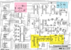
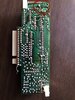
This technology is a bit old, but fun to look at because it's the functional blocks...
Anyhoo, speaking of old,
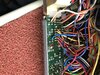
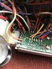
Better take a look at the on board Regulator Highlited - below.
It's an 8V takes in 13.8 volts then regulates it...
which are you supplying it 13.8?
Or are you giving it 8V from your RADIOS on-board regulator.
The newer chassis supply it with 8V.
Check for 13.8 - the thing is a linear device and if it's as old as I think it is, that thing is on a limited budget as well as time... The older Toshibas in there may be durable, but if it's having problems holding count - then the Caps need to be checked, look at the voltage off the On-board regulator - see if it's "dropping" and, if possible, look into 'scope-ing the output of that IC604 - for if it's weak, then the rest of the counter shows it...
As you said the display flashes, so if you're not having problems "listening" to the channel - as in it's not snapping in and out as this display flashes to signal the VCO out of lock - then it can't be LACK of signal. Potentially a harness wire that select USB or LSB - or the Counters' own internal amp (IC604) to obtain this signal - isn't working. (IC604 cleans up and send it to a "divisor" mixer that offsets the USB or LSB when it's toggled on) This may explain the warm up process.
The IC604 buffers this signal it's a prescaler to buffer the IF - it cleans it up. So if those caps that power it or the line AFTER (the Output of IC604) are bad, the weak signal can affect "Capture" of the clocking signal.
These IC's used "Caps" and outputs are pretty hefty so they don't pull down the lines from the VCO - tells me it's internal to the counter - else you'd have problems with operating the radio from it pulling down the IF signals the radio uses - and at the same time it sends it to that counter.
Otherwise - you'd notice weak to "really quiet" stations blaring in and out erratically while this warm up occurs.
IF the thing flashes like that and your radio has sounds like a rushing swirl or again, a snap to Lock, and mutes when it's not (Radios' Green RX Light does not means LOCK - just it's getting power) - then IT WOULD be the Radio causing this - for the Frequency counter needs a good strong signal but if the radio couldn't produce it - like it was weak, that thing wouldn't even show a frequency because it has none strong enough to do so.
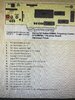
Found a couple of PDF's to help - they're searchable...
EDIT:
Added...
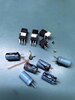
Ok, you said you replace the Electrolytic's, it is my fear there are also other line filtering caps that may add "noise" to the power supply feed, not unlike the "pops and hiss squeals" from the older radios - I've found that the Mylar or other Tantalum caps that work alongside the electrolytic's may show their age and are adding the noise factor - drowning out the signal the counter is trying to capture.