• You can now help support WorldwideDX when you shop on Amazon at no additional cost to you! Simply follow this Shop on Amazon link first and a portion of any purchase is sent to WorldwideDX to help with site costs.

TDA2003 amp getting hot

Robb, check for any removed parts "downstream" of the output capacitor.

A good friend of mine with experience using the TDA2003 told me to verify the presence of a "nuetralization circuit" (tube reference) after the output capacitor.

Without referring to the datasheet, it could be a low value resistor with a small value capacitor in series to ground.

In a misguided effort to increase audio bandwidth someone may have removed these thinking they act as a filter.
(Any frequency attenuation would be far above audible range)

Without these components installed the TDA2003 will likely oscillate (and get hot) as you describe, along with the audio sounding like hot garbage.
 
Last edited:
Robb, check for any removed parts "downstream" of the output capacitor.

A good friend of mine with experience using the TDA2003 told me to verify the presence of a "nuetralization circuit" (tube reference) after the output capacitor.

Without referring to the datasheet, it could be a low value resistor with a small value capacitor in series to ground.

In a misguided effort to increase audio bandwidth someone may have removed these thinking they act as a filter.
(Any frequency attenuation would be far above audible range)

Without these components installed the TDA2003 will likely oscillate (and get hot) as you describe, along with the audio sounding like hot garbage.
Thanks for adding in the thread, LF:

Thing is, this is the same tda2003 that is used in car stereos as an amp (using one for each channel). Doubtful that they would be limiting the freq response in such a scenario. Or that it couldn't run in a CB radio. My guess is that the presence of RF and necessity for keeping fundamentals and harmonics out of the audio path would be the reason for additional filtering. This radio was NOS right out of the box w/o any mods when I got it.
As a guess . . . so long as it allows ~5khz thru, it should still allow for hifi.
 
Last edited:
The TDA2003 is a "Hi-Fi" amplifier, with better THD specs than the TA7222ap, many car stereo circuits use greater than 470uF on the output.
The transformer in the radio will reach saturation point quickly if you attempt to pass too much low-end bass response through it.

The components tied to the output are needed for stability, they aren't limiting the frequency here per se, but preventing a (lack of) feedback issue, which could/would result in a "runaway" self-oscillation.


If your radio was NIB, hate to say but you must've ended up with a lemon!
 
Last edited:
  • Like
Reactions: Robb
The TDA2003 is a "Hi-Fi" amplifier, with better THD specs than the TA7222ap, many car stereo circuits use greater than 470uf on the output.
The transformer in the radio will reach saturation point quickly if you attempt to pass too much low-end bass response through it.

The components tied to the output are needed for stability, they aren't limiting the frequency here per se, but preventing a (lack of) feedback issue, which could/would result in a "runaway" self-oscillation.


If your radio was NIB, hate to say but you must've ended up with a lemon!
Ahh; but all the real fun begins when you attempt to sort it out and bring it back.
Yes?
 
  • Like
Reactions: LeapFrog
@Robb - I worked a thread earlier today, you may need to try some of the "tricks" in it.

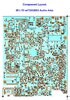
Since you have a 25' - found that Chassis layout ...

Might want to try starting at Ground Zero, the Chip itself.

Try removing all the input lines to the chip - then see if it gets hot...

upload_2020-4-17_21-26-39.png

The two resistors you should start this by removing their signal going into the chip...
  • - R52, 100K disconnects the Receiver side...
  • R53 also 100K disconnects the MIC...
With the two resistor removed, see if the oscillation continues.

If the chip still gets hot - THEN IT IS NOT FROM THE MIC OR RECEIVER - the problem is within the Chip or it's output...

From this portion of the test, leave R52 and R53 disconnected and NOW remove D 18. this removes the Driver and Final from this.

The Speaker is LEFT ALONE - still connected - so we will have to KEEP it connected for this test.

Keep Mic cord connected - it handles the speaker ground Pin 1 and 4 - but the Radio will not TX and PA will not work - but that got ruled out earlier - when the amp still gets hot - but those sections were not connected.
  • now we've disconnected nearly all the parts it affects in an effort to prevent the oscillation - does the Chip still get hot?
If so, the Chip and its' support parts are all suspected and need to be checked.

If the Chip stays cool, then look into the TX strip and Limiter Circuit for failed or bad parts...

If the Limiter section has a failed part or has a shorted cap - Reinstall D18 but Remove VR5 - the Modulation Adjustment trimmer...and try this step again...
  • If the amp no longer gets hot, the Limiter section is causing this loop. So check the most likely parts that can fail - like the Caps C70, C144 and C91 (By D9/C118/R56/R51 - by Front Panel - Mic Jack side)
  • It also serves to note,
    • Since you said Oscillation requires some kind of feedback loop
    • The Limiter is the only circuit in the radio that actually provides the feedback loop from the TX strip to the Mic amp section. EVEN THOUGH WE TERMINATED THIS LOOP BY DISCONNECTING THE MIC AMP CIRCUIT thru R53
    • It does not rule out another problem of loading the Audio Amp with a dead short circuit within the Limiter circuit
This also raises another symptom solution...
  • If the Audio Amp is COOL no longer oscillating, by disconnecting R52 and R53 - Reconnect R53.
  • Does The oscillation start up again - Chip getting Hot?
    • Be sure to Remove VR5 - does oscillation stop? Suspect Limiter and Mic Amp circuits.
  • See caps list above for Limiter components.
Echo boards added or WX Alert?
  • May want to remove these temporarily. IF Echo or some type of Talkback is installed, this needs to be removed so we can isolate the circuit causing this condition.
Once the Oscillation stops, we may have found the circuit or it's tap that was causing this...
If it still gets hot then we've isolated it to the TX strip itself and or the Audio Amp...

But to verify that the TX strip is causing this - the AMP needs to remain connected to it for this last test to validate the oscillation or a loop problem exists ELSEWHERE.

The TX strip parts...mostly the RF current quenching filters like C68 and C71, By D18, or C43, By the Final and or C158 - By Driver...

upload_2020-4-17_21-56-16.png

I can say with near certainly that you may have some caps that need to be replaced simply due to age.
 

Attachments

  • Cobra25LTDNEWERChassislayout.jpg
    Cobra25LTDNEWERChassislayout.jpg
    1.2 MB · Views: 5
Replace C63 - You have a wire running out of it - it needs to be a cap.

But you don't have it in there so Instead you have a Black wire running out of the Ground side of the Outline.

Where does that black wire go?

upload_2020-4-18_19-24-54.png

You "cut it off" in your overhead shot...

I'm asking because you have a missing part of the loop the Chip needs to work...
You sent me this photo in the PM - I'm asking because the wire goes to GROUND of that missing CAP.
 
Last edited:
Thar black wire leads up to the front of the radio just in front of C121.
It looks like it is going from ground plane to ground plane.
???

Do you have the schematic for this radio- BTW?
Don't know the value of C63; no schematic.

Thought that wire looked out of place; but not familiar with this radio.
Customer said he bought it NIB off of Ebay, FWIW.

20200418_171012.jpg
 
Last edited:
Checking - and also to drop a word with you, the schematic of the '25 is the Closest I got for you and I to work with, each time I refer back to the TDA 2003 - it uses the C63 (or C35 in that same spot labeled as such on the '29) a 47uF Electroltyic - and for that wire to run off somewhere, I'll have to look further into the Parts Layout...this isn't over yet...

W85 is a Ground point and points towards front panel side - it is obvious this wire is simply looping back to another ground...it is by MIC 3 which is the TX toggle

Remove the wire from the spot where C63 would go first. This may help you determine if this wire was needed for any function and it is likely by your word - just a black wire running from ground to ground.

Recommend that you remove that jumper, for both sides if you followed the wire, are board ground - this actually induces a ground loop that can add noise.

Remove that jumper and install the C63 a 47uF 25V - let me know how it goes...

The wire may have been for an Echo board since the Ground wire was close to the MIC wire corner of the board with the various breakouts from that section Keying, Speaker Return - Audio for Dynamike - CB/PA routing - it all begins in that corner.
 
Last edited:
Handy Andy, I want to buy YOU a beer!
Thank You, Sir.
It works now w/o heating up.

The TDA2003 IC is as cool as a cucumber now; barely gets greater than skin temperature.

What concerns me, is the fact that my customer got a radio advertised as 'NOS/NIB' on Ebay.
This thing had been hacked ! ! !

But what REALLY concerns me, is where the W85 ground wire was meant to go?
I pulled it out.

Haven't tested the oscillation yet; but I'll bet it is playing nice now. Bet that IC was in self oscillation because that cap wasn't in there. Put in a Nichicon 47uf 25v from my cap stash.

I searched in a lot of places for that schematic, but could not find it.
Odd that a Cobra 25 LTD Classic schematic with the TDA2003 chip is unobtanium.

Andy, you also created a lot of special info that people that come to this forum can use.
So thanks again!
 
Last edited:
Well, don't thank me, thank those that still think to turn to places like this.

Is the Volume ok?

I exist, because you exist - (@Slowmover Philosophy inclusive...) Just fewer words...

Did want to say though, with that wire come the curiosity of "where does the "bread" go?"
upload_2020-4-19_11-38-53.png

I think W85 may still need to go somewhere, but the person whom did that wire mod may have used the wire as a jumper from that spot - When you remove C63 (C35 - on '29) the GAIN goes WAY Way up - and it's why that chip heats up - it goes into Self Oscillation if that Pin 2 gets left open - When he "grounded" the pin they left Pin 1 full gain. (Doesn't squeal per our hearing it now rings at a higher frequency - but as you saw, it was an ultrasonic ring due to this mod)

Anyhoo, note that the "Silkscreen" tends to give you a "directional arrow" - meaning it leaves the board to arrive to a spot elsewhere, meaning - it may go to a switch or to the Dynamike control or to branch to a set of switches on the Front Panel...Note this closer-detail pic...
upload_2020-4-19_11-45-24.png

Also note too, that many of those wires "directionally" head into the front corner - as if the "loom" was there, so as the techs solder this stuff together - they "enter into the board" in a particular direction or approach - to me this means that the person did something and used a switch on the font panel to make this function switchable.

This is a common ground point for Audio - as you look further into the corner - many of the Mic leads head into this. It's my thinking that W85 goes to a soldering "step" they complete at the factory - so that wire goes to that step - again possible Front Panel don't see too many Cobra 25's with "reloops" (Well, VCO maybe)

This area and Board Screw is a tie-off point for the Mic Jack and they place a lot of emphasis on grounding and shielding - starting here.

Front panel facing you, it's the Front right corner with the component side up.

They may have re-routed a wire to take place of that ground point from somewhere else. So look for "fresh work" near, on and around the front panel.
 
  • Like
Reactions: Slowmover
Put it on the scope, and it shows no hum from the mic. Cannot see any molested solder points on the front panel pots, switches, or mic plug. Receive audio receive is now a bit louder and more sensitive. Audio IC is cool. The stock mic is a real piece of - 'work'.

Put a cap and resistor mod in it to play with it for awhile. With a 220 ohm resistor and a 470uf cap, it keys at exactly one watt and swings well over 100%. Waveform looks best when modulation is set to ~120%. After that, it boxcars pretty fast.

Radio works like it should. I've only worked on a few of these radios before; but not without a schematic. This one is a bit tricky w/o it. Sure would like to get this schematic to put in my files should this kind of radio once again come across my bench.

My guess as to how it got this way? Someone got in there thinking there were going to modify it, didn't know what they were doing, reassembled it when it didn't work as they planned, and shoved it carefully back in the box with all of the oem packing, and then claimed it was NOS and so sold on Ebay.
 
Last edited:
  • Like
Reactions: LeapFrog
My guess as to how it got this way? Someone got in there thinking there were going to modify it, didn't know what they were doing, reassembled it when it didn't work as they planned, and shoved it back in the box and claimed it was NOS and sold it on Ebay.

upload_2020-4-19_21-44-11.png

OR

...it came from a dark lab - Discovered...somewhere in the Realms Of Racks Containing Archives of those that view You Tube Videos from Ancient Technology located beep underground - lost to the world, never to see the light of Day again...

The radios' condition of being butchered, we've been seeing a lot of them lately - Donor Radios - ones that lived, fondly awaiting the day to have their handsets be held - only to give their lives under the Roughshod scalpels of Doctors with No Degrees using Lots of Caloric Degrees and Thermal BTUs' in a Vain attempt to obtain that gain to call their own - at the Expense on the Innocent ones that didn't deserve to die...

These Chassis sacrificed themselves in hopes of finding a future - just wanting, longing, needing to be put in a Vehicle, chosen - and installed by, for and with, the owners - and used in Respect...Operated in Reverence to others for Radio Checks, 10-36's and "Does Anybody Know Where I'm at?" - amongst other ramblings...

Boy...Do I need a vacation...
 
  • Like
Reactions: Robb and LeapFrog
Checking - and also to drop a word with you, the schematic of the '25 is the Closest I got for you and I to work with, each time I refer back to the TDA 2003 - it uses the C63 (or C35 in that same spot labeled as such on the '29) a 47uF Electroltyic - and for that wire to run off somewhere, I'll have to look further into the Parts Layout...this isn't over yet...

W85 is a Ground point and points towards front panel side - it is obvious this wire is simply looping back to another ground...it is by MIC 3 which is the TX toggle

Remove the wire from the spot where C63 would go first. This may help you determine if this wire was needed for any function and it is likely by your word - just a black wire running from ground to ground.

Recommend that you remove that jumper, for both sides if you followed the wire, are board ground - this actually induces a ground loop that can add noise.

Remove that jumper and install the C63 a 47uF 25V - let me know how it goes...

The wire may have been for an Echo board since the Ground wire was close to the MIC wire corner of the board with the various breakouts from that section Keying, Speaker Return - Audio for Dynamike - CB/PA routing - it all begins in that corner.
 

dxChat
Help Users
  • No one is chatting at the moment.
  • @ Wildcat27:
    Hello I have a old school 2950 receives great on all modes and transmits great on AM but no transmit on SSB. Does anyone have any idea?
  • @ ButtFuzz:
    Good evening from Sunny Salem! What’s shaking?
  • dxBot:
    63Sprint has left the room.
  • dxBot:
    kennyjames 0151 has left the room.