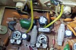
I purchased this Cobra 2000 GTL on eBay as a parts radio. I know...I know...lol. It is made in Taiwan and the board number is PC-497AB. Initially the radio would only transmit very low on both AM and SSB. That is how it arrived. The radio has since been totally re-capped, electrolytic, ceramic and tantalum caps. All voltages on IC5 (mixer) are good. Pre driver TR39 (C1973) is good I installed a new driver and final as well as a new bias regulator TR37 (C496) Everything looks good up to and including the driver TR38 (C1306)
The driver voltages are:
Base .455volts rx AM .740volts tx AM
Collector 12.95volts rx AM 6.6volts tx AM
Emitter tied to ground.
Something is not right with the bias regulator voltages, yet I have the driver set at 30mA and the final bias at 60mA.
Bias Regulator
Emitter .489volts in AM rx mode (which is good) and 1.277v in AM tx mode (which is high)
Collector 3volts in AM tx mode and rx mode (should be 2.66v tx AM and 7.28v tx SSB)
Base 1.25v in AM tx mode
I have .489 volts rx into R180 and 8.31volts tx into R180
.489 volts rx at anode of D76
3.00 volts rx at cathode of D76
Final transistor (C1969) TR36
Emitter tied to ground
Collector 12.95 volts rx 6.6 volts tx
Base 175mv rx .944 volts tx (should be about .4volts in rx AM mode)
Radio is putting out .8 watts (carrier) and goes up to 2 watts on a whistle
SSB does 3.5 watts max.
The radio has been totally re-aligned. Synthesizer/PLL, Receive and transmitter peaking coils are new (L45, L46,L47,L48)
So, something is not right with the bias regulator voltages ( bias diodes are good)
Base voltage on final is low in rx mode.
Any ideas anyone??