
You are using an out of date browser. It may not display this or other websites correctly.
You should upgrade or use an alternative browser.
You should upgrade or use an alternative browser.
-
You can now help support WorldwideDX when you shop on Amazon at no additional cost to you! Simply follow this Shop on Amazon link first and a portion of any purchase is sent to WorldwideDX to help with site costs.
2970 CD
- Thread starter Kung Fu Panda
- Start date
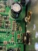
That appears to be Q50 that is missing. That is part of the voltage regulation circuit for the 8-Volt rail.
Ok it was laid on its side with the collector not being used. Q50 would be a 2712GR from what I find.
My apologies, I was wrong with my initial response. The transistor beside it is Q50, the part that is missing in the photo is actually a diode. It is D66 only 2 of the 3 pads are used in the circuit. It still should be soldered flat, I would think. I don't see any reason it would need to be soldered like you describe.

The datasheet that I was able to find showed the MA28W as a Varistor Diode with a forward voltage drop of around 1.2V (multiple part suffixes to denote different forward voltage, but all were around that area) and had a predictable voltage vs. temperature curve. Seems they were meant for temperature compensation for voltage regulators or temperature sensing. I don't think that part is available anymore though, and based on the way that part is mounted, my best guess is that it contains 2 standard diodes in series and it's mounted sideways like that so that the 1.2V is dropped across both. Mounting it properly would only make use of a single diode with approximately 0.6V. I'm just guessing here, so I could be wrong. You could always use a DVM in diode check mode and check the polarity and voltage drop from the unused pin to each of the soldered pins.
Surface-mount diodes in that package come with one diode, two diodes, both in series, or with cathodes on a common pin, or anodes on a common pin.
The board was laid out for one type, but the part that's "sideways" has the wrong pinout. It's turned the way you see it to satisfy the proper circuit hookup with the part they could get. Looks as if a diode with the correct pinout was not available.
Or maybe they flubbed the board layout for that part? We'll probably never know.
The circuit uses a diode with two junctions in series to double the temperature response you would get from a single diode. It's there to stabilize the regulated voltage over temperature changes.
A pair of 1N4148 generic diodes in series will work in place of that part, but the physical hookup will be awkward and fragile.
73
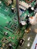
I've attached 2 images of the pad and trace layout of those parts and the surrounding components. The first image shows how the original part was connected as well as how the sideways part was connected. The second image shows how it could be done using 2 discrete diodes, such as two 1N4148's. The pad that I marked with a yellow 'X' appears to be unused and not connected to anything else, so it could be used as a tie point. The 1N4148 diode is available in a few different SMD packages that are very small and would fit across those pads fairly neatly without being fragile. Using two 1N4148 diodes in a standard through-hole package would be fragile and risk tearing the pads off the board.
My question is, the original diode that was mounted sideways in that location, did it fail? Why did it have to be removed? Was it removed only because it was mounted sideways? If that is the case, just solder it back in place in the same sideways position it was before. That's just how they came from the factory. I have an RCI-63FFC4 that I finally got around to examining today and it has the same sideways mounted package in that location.


My question is, the original diode that was mounted sideways in that location, did it fail? Why did it have to be removed? Was it removed only because it was mounted sideways? If that is the case, just solder it back in place in the same sideways position it was before. That's just how they came from the factory. I have an RCI-63FFC4 that I finally got around to examining today and it has the same sideways mounted package in that location.
Thanks for all the help, opened up the radio and it fell out took me a while to find where it went. The two legs that were soldered were not there they stayed on the pads. Radio mabey was messed with I dont know. Ill give it a shot wish me luck, again thanks for the help....
blasphemy000 - Nomad thanks for the help worked like a champ back in business