• You can now help support WorldwideDX when you shop on Amazon at no additional cost to you! Simply follow this Shop on Amazon link first and a portion of any purchase is sent to WorldwideDX to help with site costs.

Ranger RCI 2995DXCF MOSFETS

Ranch55

Sr. Member
Jan 18, 2016
764
975
103
Fredericksburg, Texas
I have been working on my radio because the amplifier board was not working properly.
I replaced all four amplifier mosfets and the 2 (two), driver and a single final.
I made no initial adjustments.
When I applied power, at first all seemed okay. I keyed the mic and immediately things went south.
Long story cut short, I disconnected the amplifier section from the radio section. The radio final was dead shorted across all three leads. The driver was still good.
I replaced the final with a new final again.
Now at this point was my utter confusion. The information on line anywhere and on cbtricks, does not correspond with the new DXCF with MOSFETS. I was specifically looking for driver and final biasing.
I found it here.
A big shout out and thanks to "Handy Andy" for one of his post writeups.
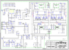
I pulled the shorting board, connected my DVM across TP7 and TP9, and set the current bias on the driver to 50ma.
Then I connected the meter across TP7 and TP8, set the current bias to 50ma.
Then I installed the shorting board and checked the gate voltage on both mosfets. They were very close to each other. Driver was 3.681 volts. Final was 3.673 volts.
I pulled the shorting board and double checked the bias current again on each. They both remained at 50ma.
The radio is receiving well and transmitting well.
My conclusion is that the radio output was overdriving the amplifier section.
VR13 and VR11 adjustment positions ended up significantly different than what the were originally.

Tomorrow, I will go after the amplifier section.
 

Well, damn the bad luck.
I installed 4 new mosfets in the amplifier section.
Very first key up into the amplifier and all 4 mosfets started going off like Roman candles. The top blew off all four of them, for the second time.
BUT, after bypassing the amplifier again, the radio itself was still performing just fine, on receive and transmit. With about 25 watts PEP output ......
I sure would like to find a complete schematic for the 2995DXCF with all MOSFETS in radio and amplifier section.
 
Check your RF amp board...

Got this from CB Tricks...

Board # upload_2021-5-6_21-53-57.png


upload_2021-5-6_21-53-9.png

upload_2021-5-6_22-0-3.png
If this is your board, go here...
http://www.cbtricks.com/radios/galaxy/dx94hp/index.htm

Under RF Amp board...

Please notice in the bottom Right comer, the GATE voltage setting procedure - CAREFUL with this - set it lower than this value to save the Amp board
  • - when it heats up, the voltage at the gates rise right along with it - keep it lower than 4.5 volts

- DONT OVERTHINK THIS!
 

Attachments

  • upload_2021-5-6_21-39-24.png
    upload_2021-5-6_21-39-24.png
    3.2 KB · Views: 30
  • upload_2021-5-6_21-39-56.png
    upload_2021-5-6_21-39-56.png
    859.2 KB · Views: 38
  • Like
Reactions: NZ8N
Thanks very much Handy Andy.
This is exactly what I was needing.
I knew V2 was to adjust something, but didn't want to just go and starting things without some info.
I suspected some high voltage on the mosfets.
I'll be checking this today or tomorrow.
Got some plumbing work gotta do today.
Always something needing worked on out here on the ranch.
 
Well okay "Handy Andy" .........
I was able to get the amplifier finals bias voltage set to 3.994 volts.
When I reached that voltage, it was as good as 4 volts in my book.
The schematic indicates to set the bias voltage to 4.5 volts, but I elected to follow your advice and go with 4 volts.

The amplifier section is now performing as expected, 148~151 watts PEP output.
The output audio looks clean on the scope as well as the output power.
Now I just need to put the whole radio back together.

Thanks so much for your input. (y) (y) (y)
 
I believe that is a misconception by many folks.
Setting the radio driver and finals should be by milliamps, not by voltage.
As you can see in my post above, when setting the radio mosfets by milliamps, the voltage came out to "almost" 3.7 vdc .....
The current bias will be more consistent throughout than by setting by gate voltage.
 
isn't the mosfet final version supposed to be set by voltage not miliamps?

NO, NO, NO, NO, NO!

The exact voltage required to get the desired "Idle" current through a MOSFET will differ from one part to the next, and from one brand to another of the same type number.

Every batch we buy gets the "Vth", or "threshold voltage" tested and marked on the back of the part. This way a matched set is simply four parts with the same reading noted on the back.

Setting this adjustment without a current reading is playing pin-the-tail-on-the-donkey.

73
 
Setting this adjustment without a current reading is playing pin-the-tail-on-the-donkey.

Can I re-quote you on that?
:)

I wish the MOSFET amp board had such a provision of a jumper in which to set mA - they don't at least since the RCI side of it took over. They don't provide that breakpoint. You'll have to follow a different "idle" procedure - similar to Finals on RCI's 69, or AT6666 - you have to disconnect the board from all RF input except power supply DC and JP7's TX ON,

Set up the power supply thru your Ammeter (+) lead and trim Bias watching the mA results you'll have an intitial "Base" mA power consumption reading you start out as your "BASIC"- and the climb curve - on a typical DVM set your meter to 200mA or 2A (2000mA) just so you can see the "switch on - voltages" - once 100mA RISE increase in Power draw is achieved, better stop there, for the MOSFET's are not all perfectly set, but in setting to the CONSERVATIVE side of the voltage turn on threshold, the one or two that turn on in the entire set - that trigger on using the lower levels of power- won't stay latched on AFTER the RF power is REMOVED or turned off...

For the OP @Ranch55 - and everyone else...

The purpose of the mA draw setting - SEEMS to be a throwback to the Bipolar days...

Yes, some things never change...

It's when the DATASHEETS, DIODES, The MOSFET itself and all the parts that TRIM it,

Resistors, Potentiometers Capacitors - even the BOARD designs - all play a roles in how much turn on POWER (not just voltage) is going to Hit the Gate. Tolerance - the performance of the end result and how well the result can be maintained....that is one of many conditions you/we/us have to COMPENSATE for when things that look great in the Lab, are put to real world work - doesn't always translate to EXACT values.

Everything isn't 100% perfect, nor is the environment it's used in.

So temperature, power supply, ambient stray RF noise - all play a role - so don't overthink a problem and believe you found a quicker way to get back on the air.

Am I wrong? On the radio isn't the mosfet final version supposed to be set by voltage not miliamps?

Yes, GATE's turn on using VOLTAGE -
  • BUT! In order to know that Gate's Voltage Turn - on REQUIREMENT.
  • REQUIRES you to monitor the Drain To Source "Turn on Resistance"
    • A dynamic CURRENT (Amperage Draw) measurement of turn on resistance to start the flow of power thru the output - those terminals - the MOSFET being (acting) Linear as a Bipolar' Switch.
    • Functioning as if it's a Bipolar just as it turns on - a VERY narrow window

To All Readers...

How many posts do YOU need to make before you finally realize how many POSTS the rest of us have done up for your enlightenment that tell you that YOU DO NOT Set GATE On, Voltage using "Voltage".

You must use - the mA trickle on Threshold Switching thru Drain to Source (Bipolar; Collector to Emitter) - it still must be followed.
 
Last edited:
That's how we set bias when no test jumper point is built in.

Set each trimmer for zero voltage. Key the mike, note the reading. This current drain is now your "reference", the starting point. Each trimpot gets set to increase this reading by the desired idle current. The difference between reference current draw, and increased draw when the trimpot is turned up.

A so-called differential measurement.

73
 
Set up the power supply thru your Ammeter (+) lead and trim Bias watching the mA results you'll have an intitial "Base" mA power consumption reading you start out as your "BASIC"- and the climb curve - on a typical DVM set your meter to 200mA or 2A (2000mA) just so you can see the "switch on - voltages" - once 100mA RISE increase in Power draw is achieved, better stop there, for the MOSFET's are not all perfectly set, but in setting to the CONSERVATIVE side of the voltage turn on threshold, the one or two that turn on in the entire set - that trigger on using the lower levels of power- won't stay latched on AFTER the RF power is REMOVED or turned off...

Okay, I did just exactly the procedure above as stated by "Handy Andy". I had considered this before.
I set the Ammeter up inline with the power supply as above, no RF.....
First, I checked the current as it was since I set the gate voltage at 4 vdc previously.
The current was 1.752 amps at 3.995 (4) vdc.
I turned (V2) the current down to minimum which was .027 ma ......
I added .100ma and then turned the current up to .127 ma using V2 ......
Then I checked the gate voltage at this current draw.
Gate voltage is 3.729 vdc at .127ma current.

The radio is performing just fine with a slight increase in PEP outpower in SSB ....
155 ~ 158 watts PEP output.
Seems to me the radio is performing slightly better with less gate voltage and much less current draw.

I typed up this procedure, printed it and added it to my notes for this radio.
Big shout out and THANKS to "Handy Andy" ........
 
You are welcome!

Run the Gates' as low as you can stand for power - it will save a lot of miles on you and your radio including - power supply and your electric bill.
 
  • Like
Reactions: Ranch55
Just because a MOSFET is a voltage controlled device, does not change the basic procedure for setting idling bias current. Tubes are also voltage controlled but, the bias voltage given is just a close figure that is always set by the specific idling current, given in the datasheet for a particular class of operation.

The turn on voltage for any device, simply varies too much from one production run to another, to ever begin to rely on a voltage setting alone. Even with a bipolar transistor that has a fairly consistent base emitter voltage drop of .6 volts, we didn't just set bias to .6 volts and forget about confirming the idling current ma.

To be frank, the gate threshold min and max ratings are only useful to me, to insure I start with a bias voltage that is below the minimum and dial it up until the desired idling current is reached. We also want to make sure the bias circuit can provide the maximum threshold voltage, so that it can be set to run any replacement transistor, with the same part number in the future.

To simplify, we should remember that bias is a function of how much power is dissipated by the DC. That's why data sheets provide a specific idling current for any linear device at a given power supply voltage and class of operation. It is only when the device is drawing the stated current with the specified operating voltage applied to the part, that we can accurately determine if the part is dissipating the right amount of power in DC, to reach the desired conduction angle.

It is not even remotely possible to do this from the bias voltage alone. However, if you know the operating voltage being applied to the part, you can set bias (and DC dissipation), by just measuring the idling current.
 
Last edited:

dxChat
Help Users
  • No one is chatting at the moment.
  • @ Wildcat27:
    Hello I have a old school 2950 receives great on all modes and transmits great on AM but no transmit on SSB. Does anyone have any idea?
  • @ ButtFuzz:
    Good evening from Sunny Salem! What’s shaking?
  • dxBot:
    63Sprint has left the room.
  • dxBot:
    kennyjames 0151 has left the room.