
The Kris Power Pump is a base linear with one baldie tube driving two 6LQ6 tubes. Radios small enough to match that single small tube's drive needs no longer exist, pretty much. Other folks have rewired the driver socket to make a straight 3-tube amplifier. This customer didn't have a set of 3 matching 6LQ6 to try that, so this one became a straight 2-tuber. At least this way it will tolerate the 30-plus Watt peaks from a typical "black" base radio.
The radio's drive power will get redirected from the driver socket where it feeds into now directly to the cathodes of the two final tubes. "Directly" as in through a pi-network input-matching circuit. The front panel has only two "Tune" controls, one for the driver tube's plate circuit and one for the finals. The front-panel "Drive tune" control will now be a fine-tune adjustment for the input circuit's 50-ohm impedance match.
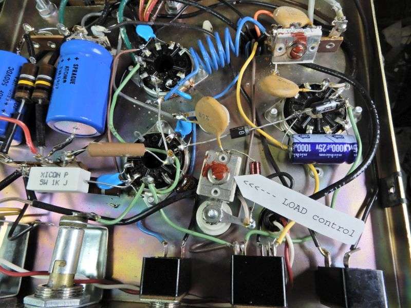
So where is the "Load" control? It's a ceramic compression trimmer cap found below the chassis. So long as you always use the same drive power, this will only need to be set once. And as you change frequencies, the final Plate Tune will take care of that.
After pulling the driver tube out of its socket one last time, first cut the orange wire at the front edge of the relay circuit board. This wire takes 400 Volts DC to the driver's plate circuit.
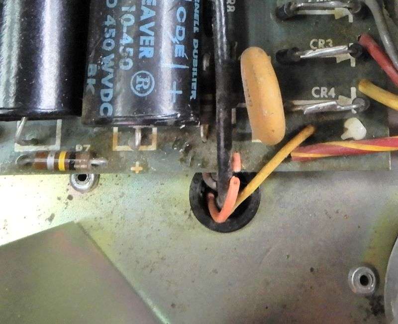
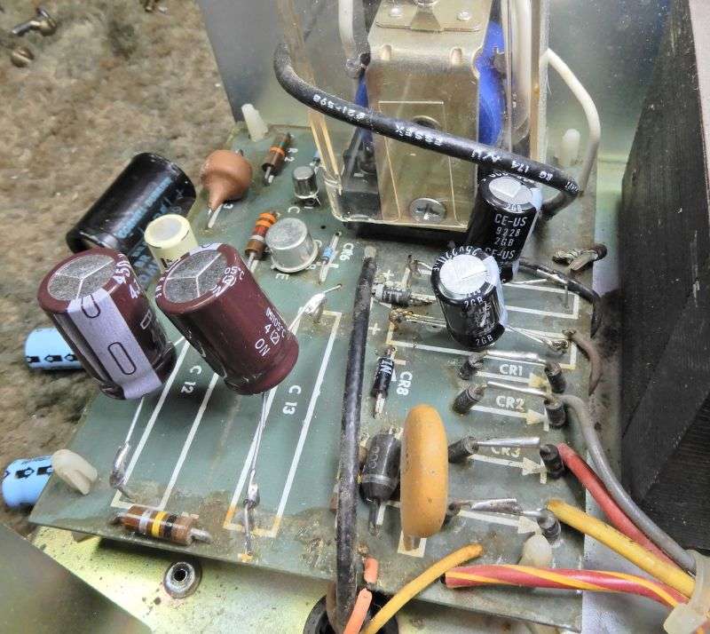
The four filter capacitors on the relay board have been replaced in this pic. If I had glanced at the schematic a bit longer I would have realized that the two 47uf 450 Volt caps on this board are needed ONLY to power the driver tube. The one that's not getting put back in. Coulda just skipped putting those in altogether. The two smaller 220uf 25 Volt caps nearer the relay are a "must" replace. If you want the relay circuit to work, at least.
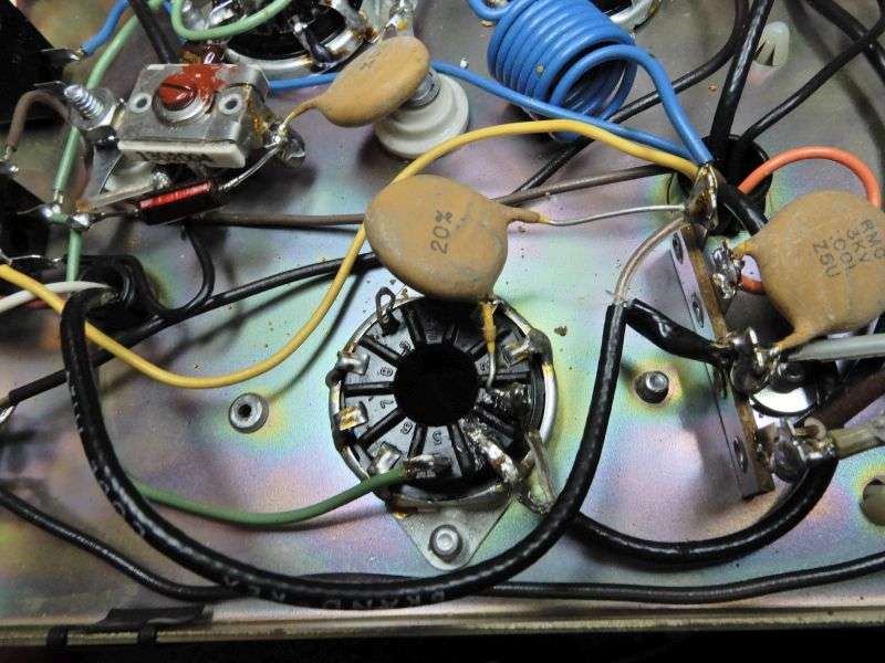
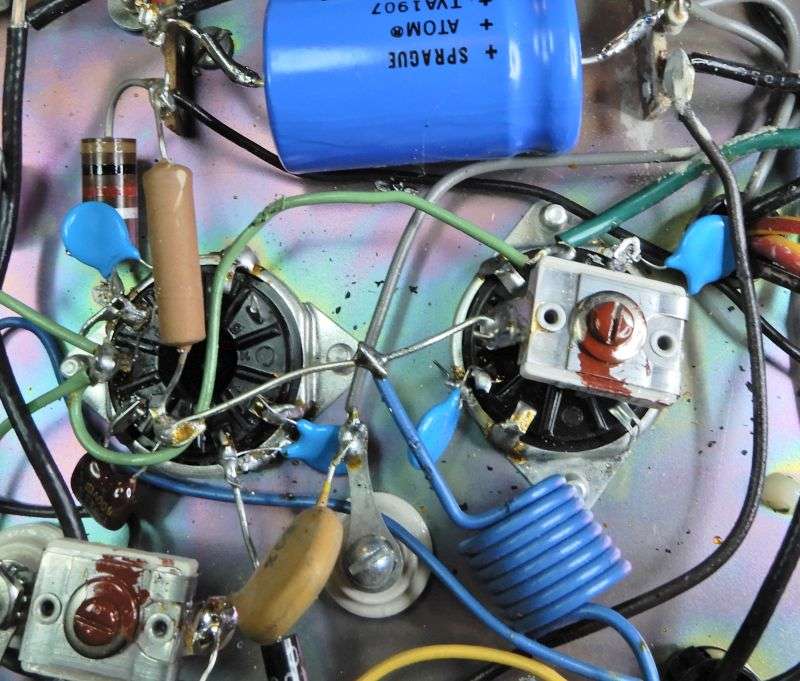
Here's what the driver socket looks like before anything is changed.
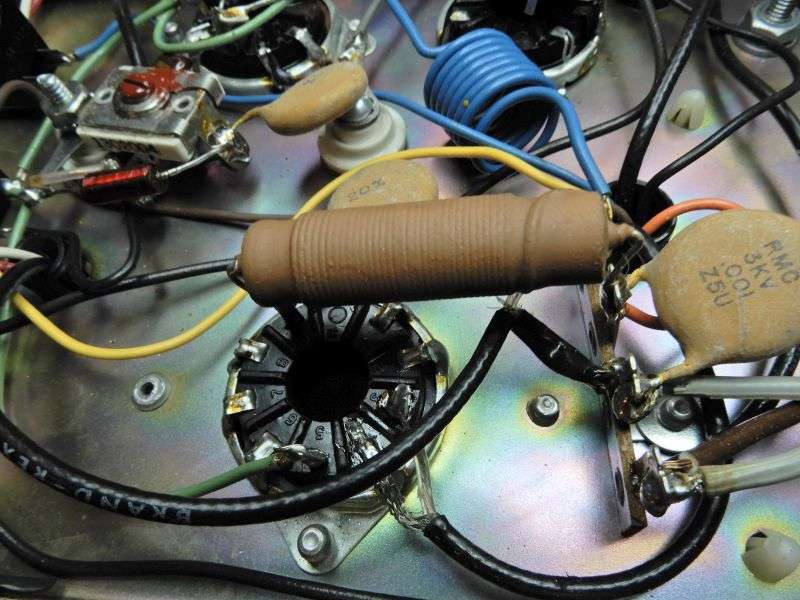
First, the brown RF choke gets removed. Next the fat disc capacitor gets unhooked from pin 9 and moved to pin 2. The coax already on pin 2 has the radio's drive power coming down from the relay.
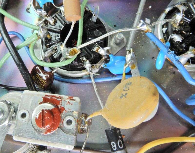
Now a 1N5408 or suitable rectifier diode gets its cathode (banded end) soldered to pin 4 of the socket where the green wire feeds in 6.3 Volts AC. Any unused pin on the opposite side of the socket will do to take the other end of the rectifier and the NEGATIVE side of the 1000uf 25-Volt filter cap. The positive side of the cap gets grounded.
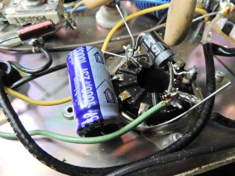
The other 1N5408 or sub gets its cathode (band) soldered to the socket lug with the first rectifier and the filter cap. Dont insert the banded-end lead too far into the socket lug. We'll need the full length of this diode to reach pin 2 of the front final tube socket.
Next the lugs for pin 6 and 2 of each final socket have to be unsoldered from ground.

Now is probably a better time to remove the mica compression trimmer cap from under the rear final tube. We'll need it later, but I didn't move it until later in the process.
The 2-Watt resistor grounded to the front final tube socket had to be moved to get the pin 6 lug free on this one.
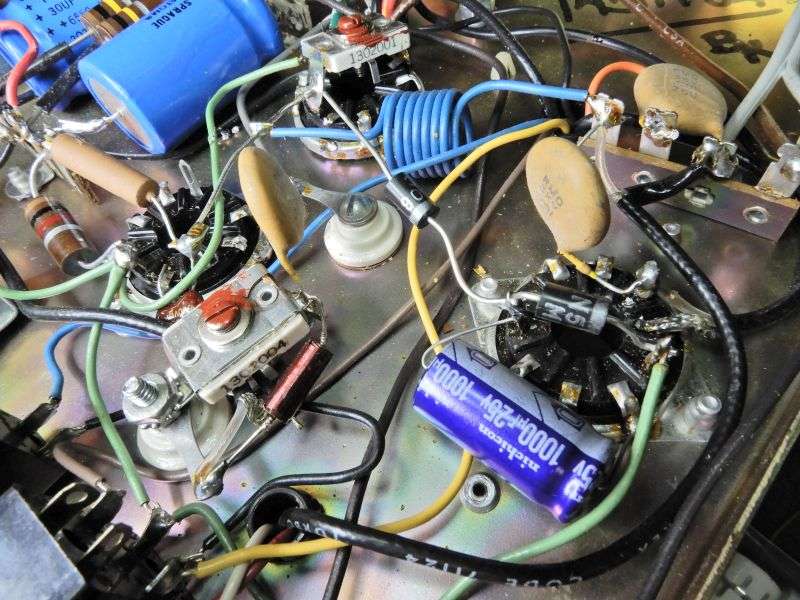
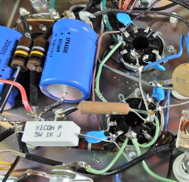
The four .01uf disc caps each get installed on pin 2 and 6 of both final sockets.
The free anode (no band) end of the rectifier diode now gets soldered to pin 2 of the front socket. Go ahead and solder the cap on pin 2 of the rear socket. Nothing else gets connected to that lug.
The final sockets get a wire from pin 6 of the rear tube to pin 6 of the front tube. The 1K 5 Watt resistor goes from pin 6 of the front tube to the ground lug where two small coax shields are grounded.
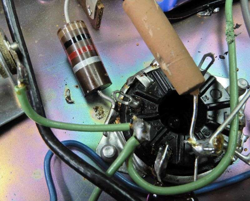
Last detail is to shorten the driver's plate coil down to five turns. Reconnect it to the same tie-strip lug as before. The compression trimmer cap that was removed from the rear final socket now gets soldered to the lug where the coil is soldered, and to the ground lug on the tie strip.
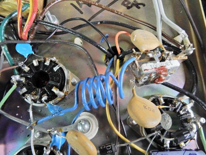
This will make the trimmer cap the input-tuning "coarse" adjustment. If you set the front-panel driver control to the center of its travel, and set the trimmer cap for minimum input-side SWR, the front-panel knob becomes a "fine" input match control.
Naturally there will be some back-and-forth, getting the final load trimmer cap set for max swing, the final plate tune for a peak, and the input trimmer cap for lowest input SWR.
This setup should be okay up to around 30 or so Watts PEP drive before it gets uncomfortable.
Bill of materials:
2) 1N5408 or equivalent rectifier. Yeah, a 1N4001 would probably do just fine.
1) 1k 5 Watt resistor. Wirewound is okay.
4) .01uf disc caps. I wouldn't use a voltage rating below 1000, but feel free to walk on the wild side.
1) 1000uf 25-Volt electrolytic cap.
Your mileage may vary, and anyone foolish enough to reach inside of this kind of amplifier has only him (her) self to blame if it all ends in tears.
73
The radio's drive power will get redirected from the driver socket where it feeds into now directly to the cathodes of the two final tubes. "Directly" as in through a pi-network input-matching circuit. The front panel has only two "Tune" controls, one for the driver tube's plate circuit and one for the finals. The front-panel "Drive tune" control will now be a fine-tune adjustment for the input circuit's 50-ohm impedance match.
So where is the "Load" control? It's a ceramic compression trimmer cap found below the chassis. So long as you always use the same drive power, this will only need to be set once. And as you change frequencies, the final Plate Tune will take care of that.
After pulling the driver tube out of its socket one last time, first cut the orange wire at the front edge of the relay circuit board. This wire takes 400 Volts DC to the driver's plate circuit.
The four filter capacitors on the relay board have been replaced in this pic. If I had glanced at the schematic a bit longer I would have realized that the two 47uf 450 Volt caps on this board are needed ONLY to power the driver tube. The one that's not getting put back in. Coulda just skipped putting those in altogether. The two smaller 220uf 25 Volt caps nearer the relay are a "must" replace. If you want the relay circuit to work, at least.
Here's what the driver socket looks like before anything is changed.
First, the brown RF choke gets removed. Next the fat disc capacitor gets unhooked from pin 9 and moved to pin 2. The coax already on pin 2 has the radio's drive power coming down from the relay.
Now a 1N5408 or suitable rectifier diode gets its cathode (banded end) soldered to pin 4 of the socket where the green wire feeds in 6.3 Volts AC. Any unused pin on the opposite side of the socket will do to take the other end of the rectifier and the NEGATIVE side of the 1000uf 25-Volt filter cap. The positive side of the cap gets grounded.
The other 1N5408 or sub gets its cathode (band) soldered to the socket lug with the first rectifier and the filter cap. Dont insert the banded-end lead too far into the socket lug. We'll need the full length of this diode to reach pin 2 of the front final tube socket.
Next the lugs for pin 6 and 2 of each final socket have to be unsoldered from ground.
Now is probably a better time to remove the mica compression trimmer cap from under the rear final tube. We'll need it later, but I didn't move it until later in the process.
The 2-Watt resistor grounded to the front final tube socket had to be moved to get the pin 6 lug free on this one.
The four .01uf disc caps each get installed on pin 2 and 6 of both final sockets.
The free anode (no band) end of the rectifier diode now gets soldered to pin 2 of the front socket. Go ahead and solder the cap on pin 2 of the rear socket. Nothing else gets connected to that lug.
The final sockets get a wire from pin 6 of the rear tube to pin 6 of the front tube. The 1K 5 Watt resistor goes from pin 6 of the front tube to the ground lug where two small coax shields are grounded.
Last detail is to shorten the driver's plate coil down to five turns. Reconnect it to the same tie-strip lug as before. The compression trimmer cap that was removed from the rear final socket now gets soldered to the lug where the coil is soldered, and to the ground lug on the tie strip.
This will make the trimmer cap the input-tuning "coarse" adjustment. If you set the front-panel driver control to the center of its travel, and set the trimmer cap for minimum input-side SWR, the front-panel knob becomes a "fine" input match control.
Naturally there will be some back-and-forth, getting the final load trimmer cap set for max swing, the final plate tune for a peak, and the input trimmer cap for lowest input SWR.
This setup should be okay up to around 30 or so Watts PEP drive before it gets uncomfortable.
Bill of materials:
2) 1N5408 or equivalent rectifier. Yeah, a 1N4001 would probably do just fine.
1) 1k 5 Watt resistor. Wirewound is okay.
4) .01uf disc caps. I wouldn't use a voltage rating below 1000, but feel free to walk on the wild side.
1) 1000uf 25-Volt electrolytic cap.
Your mileage may vary, and anyone foolish enough to reach inside of this kind of amplifier has only him (her) self to blame if it all ends in tears.
73
Last edited:
