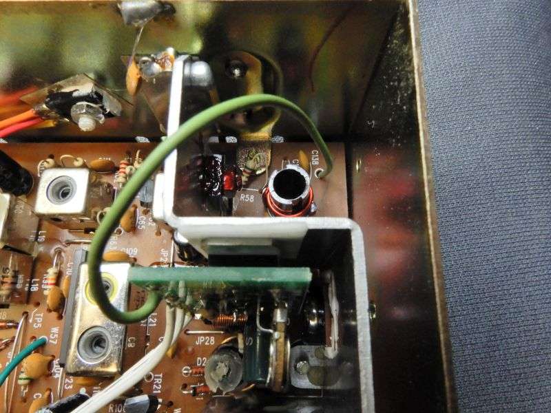
Was asked about this in a previous thread , The radio is usually tuned to spec's which would look very close to 5 to 20 give or take a watt either way at 100% Modulation , The cap/resistor mod is then applied. (No need to cut limiter what so ever) There are many different valued caps and resistors used in these mod's that will work , I've used 35 volt 1000uf caps over the years for this along with 1 watt resistors for my radios DK ,usually 68 ohm to 82 ohm will get me 1 to 2 watt DK on my radio 100 ohm should be right around 1/2 a watt if that's what one would desire (usually that would go well on a variable drive if need be) On the Cobra 29 the cap will go at JP36 which is usually a jumper wire on the board right in front to the slight left of the final ,after the radio has been tuned as stated above , you can remove this jumper and insert the cap with the (negative side towards the final), you then turn the radio over and from end to end of the caps leads you can then add your resistor to the caps leads on the bottom side of the board,this will give you your desired DK (then clip the leads), If your radio was swinging 20 after you had tuned it , it will now swing that 20 from the desired DK you were looking for . I use 1 watt resistors because smaller resistors can really get hot and the 1 watters have seemed to handle these mods just fine without major over heating. After the mod is complete ,the radios audio will be off the scale with a stock mic. usually 12 o-clock on the radios mic gain will be all that is needed , I've found that RK-56 mic's work the best along with the 636s or just the stock mic. But the NC mic's surely pick up no back ground at all and can really give the base Station quailty sound when set right on these modded radios. If a variable drive comes to mind with these mods ? You can use the RF gain on the radios (this is just one way) follow the wires from the rf gain to the board ,unsolder from the board (you will then need to add a jumper on the bottom of the board from where the wires of the rf gain were so the rf gain is wide open) then you can take the wires from the rf gain back through the front of the radio pushed through to the bottom side of the radio (you will have plenty of wire to work with from the rf gain) route the wires accross the bottom side of the board stright accross to the end leads of the resistor you used for the radios DK , now you have a varibale drive from your rf gain control. (if you got your wires backwards , just reverse them. (-: of course with any mod's , a decent watt meter and dummy load will surely help the cause. As I said before ,it's not a perfect science but they work all the same and work well as long as one knows where to set his mic gain , because these mod's can give a radio knock you out of your seat nasty loud audio !! They surely help with the drive of any amp , but like I said , you really do not need any kind of power mic with these mods , RK-56 being the best as far as IM concerned. Have fun. (-:

You are using an out of date browser. It may not display this or other websites correctly.
You should upgrade or use an alternative browser.
You should upgrade or use an alternative browser.
-
You can now help support WorldwideDX when you shop on Amazon at no additional cost to you! Simply follow this Shop on Amazon link first and a portion of any purchase is sent to WorldwideDX to help with site costs.
Cobra 29 LTD Classic Swing Mod
- Thread starter Switch Kit
- Start date

Shadetree Mechanic
Delaware Base Station 808
Bump for JP36 fun.
The only problem I've had with this particular mod is that it will eventually spot burn the pot causing an open at that point. I suggest using the TIP transistor mod. I'm running it now and it's crazy smooth. Only downside is that I had to buy 25 of the TIPs and caps just to build one.. So I'm just building some and keeping them handy if some local guy needs one.
Attachments
You can also see this link, From @nomadradio he designed a simple "peel 'n Stick" board that is similar to this concept...
![TIP-120SWINGMOD[1gif].GIF](https://www.worldwidedx.com/data/attachments/34/34825-df2972fa11e17ac085d82b17f7618e1f.jpg "TIP-120SWINGMOD[1gif].GIF")
OR a more detailed step by step...

OR a more detailed step by step...
Last edited:
Would there be any benifit to mounting the TIP to heatsink? I would think (read no idea) that the operating voltage was low enough that it would not generate enough heat to cause concern?You can also see this link, From @nomadradio he designed a simple "peel 'n Stick" board that is similar to this concept...
The TIP120 is a "big transistor" read this as a power device, that DISSAPATES power as it is used.
You have to look at how "power" is distributed thru the radio.
The Final takes in the biggest amount of power across itself to make the 4 watts output (work with me here)
The Driver takes in a little less, about 1/4th that power - so it generates about 1 to 1-1/2 watt - so it needs less power (Voltage and Current) to accomplish this.
The TIP120 changes the power level, provides power to what the Driver DELIVERS to the Final - does not Power the Final - that hasn't changed.
Even though you affect the Driver - remember there are two types of power present on this line from the Modulation Transformer to these two sections.
So when you review the circuit, you're affecting this DC Bias and some audio passing thru too, but most of the AUDIO Power passes by the transistor - it goes thru, bypassing the Transistor, the path of least resistance - that CAP accomplishes this.
You have to look at how "power" is distributed thru the radio.
The Final takes in the biggest amount of power across itself to make the 4 watts output (work with me here)
The Driver takes in a little less, about 1/4th that power - so it generates about 1 to 1-1/2 watt - so it needs less power (Voltage and Current) to accomplish this.
The TIP120 changes the power level, provides power to what the Driver DELIVERS to the Final - does not Power the Final - that hasn't changed.
Even though you affect the Driver - remember there are two types of power present on this line from the Modulation Transformer to these two sections.
- DC bias, your battery power from the power connector,
- and the MODIFIED Audio power from the out of that transformer.
It's what I call Audio + Bias - I'm taking the perspective of Power both in DC and Audio - is present at the same time - on the same line, going to a part - which changes the way that part operates and it's output.
So when you review the circuit, you're affecting this DC Bias and some audio passing thru too, but most of the AUDIO Power passes by the transistor - it goes thru, bypassing the Transistor, the path of least resistance - that CAP accomplishes this.
- the Driver still "sees" Audio power unmodified - thru that cap.
- but the BIAS, the DC stuff, is altered by the circuit
Using this method - you dissipate even less power across the TIP120 than without the cap.
So the power Transistor the TIP-120 is, makes the power change Thermally-safe enough - if you attach the "stick on" to the heat sink panel - that same one the Final and Driver use- it will dissipate the power drop across itself safely enough using that "stickypad" to transfer heat to the panel it's mounted (Stuck on) to.- but the BIAS, the DC stuff, is altered by the circuit
- DC is blocked by the cap so it has nowhere to go but THRU the transistor.
- Since its' designed to make DC variable, you control the DC power which controls the Carrier power present for your Audio Signal.Using this method - you dissipate even less power across the TIP120 than without the cap.
Last edited:
The TIP120 is a "big transistor" read this as a power device, that DISSAPATES power as it is used.
You have to look at how "power" is distributed thru the radio.
The Final takes in the biggest amount of power across itself to make the 4 watts output (work with me here)
The Driver takes in a little less, about 1/4th that power - so it generates about 1 to 1-1/2 watt - so it needs less power (Voltage and Current) to accomplish this.
The TIP120 changes the power level, provides power to what the Driver DELIVERS to the Final - does not Power the Final - that hasn't changed.
Even though you affect the Driver - remember there are two types of power present on this line from the Modulation Transformer to these two sections.
- DC bias, you battery power from the power connector,
- and the MODIFIED Audio power from the out of that transformer.
It's what I call Audio + Bias - I'm taking the perspective of Power both in DC and Audio - is present at the same time - on the same line, going to a part - which changes the way that part operates and it's output.
So when you review the circuit, you're affecting this DC Bias and some audio passing thru too, but most of the AUDIO Power passes by the transistor - it goes thru, bypassing the Transistor, the path of least resistance - that CAP accomplishes this.
- the Driver still "sees" Audio power unmodified - thru that cap.So the power Transistor the TIP-120 is, makes the power change Thermally-safe enough - if you attach the "stick on" to the heat sink panel - that same one the Final and Driver use- it will dissipate the power drop across itself safely enough using that "stickypad" to transfer heat to the panel it's mounted (Stuck on) to.
- but the BIAS, the DC stuff, is altered by the circuit
- DC is blocked by the cap so it has nowhere to go but THRU the transistor.- Since its' designed to make DC variable, you control the DC power which controls the Carrier power present for your Audio Signal.
Using this method - you dissipate even less power across the TIP120 than without the cap.
Dude... If I could grasp a 1/8 the knowledge you have.
After a few attempts I still haven't got this mod to work correctly. The radio would always over mod. Didn't look so good on the scope and then decided not to run it.
The performance was the same whether I "stuck" it on with double sided tape or drilled a hole and "installed" it with a mounting kit.
The performance was the same whether I "stuck" it on with double sided tape or drilled a hole and "installed" it with a mounting kit.
So long as the TIP transistor is only controlling the driver transistor it won't get hot enough to need a heat sink. We mount it to the Cobra 29's internal heat sink with high-temp double-sided adhesive foam called "VHB".
Never had the TIP overheat this way.
73
Never had the TIP overheat this way.
73
I'll try and offer some tips from my desk on this. and I'll let it lay in the Debris pileup afterwards...
Yes, when you "lower" dead key, you tend to "scrunch" up audio - compressing more audio than you need to and adding so much distortion in the process - its' kinda hard to beat a dead horse on this - so what is one to do?
Several ways have been accomplished with good Type-Certified success...
How?
Well, two things really...
The AMOUNT of Capacitance used in a typical AM only - read Modulation Transformer type - versux the Quxang-method of brute force AM regulation and torpedoes be (Gosh Darned)...(AT-5555 6666 and others)
The other archaic techniques applied - when using the Transformer design, well, you "pad" the Inductive results with a resistor (or two) across coils to lessen the effect and broadband (in this case reduce) the "sharp complexity" of reactive elements of the Cap, Inductor and Their Reactive "elements" results by snubbing (a better word?) in a resistor to lessen the reaction the TX strip has to the envelope event.

You already know that many radios of yesteryear used a 10-ohm resistor to lower the Driver current to prevent the Finals' "clipping" issue of saturation when you ran vehicles that wide variability of voltage for charging systems that used regulation - but oftentimes never gave consistent voltage results - I mean - 11.5 votls to as much as 14.7 volts charging system output from a typical car of the same vintage as these circuits - well they did have to maintain type-certification. They took a different approach - limit current - so don't raise the bridge - lower the water - Jerry Lewis excluded...

Please Note:
I said WATER, not River
Midlands did this quite a bit in their designs as well as Realistic - they used the 10-ohm but that too generated issues - so they went a little extra - like this...

Even the Uniden 710e
used several methods at the same time
to limit the reactive elements of
low power swings onto
HEAVY Modulation peaks...

They did not use a CURRENT limiting resistor...
BUT...
Cobra - on their 19 Plus units - Applied them to BOTH Driver and Final

Including Final getting pushed into Class C thru L601/R310/C314
For a Cobra 29 - Use as needed to lessen the Over-mod problem...

So, what am I talking about?
Well, you have options, use them to accomplish this...
You can also affect the DRIVE and Volume, let alone the TONE by adjusting the output cap of the Audio amp into the Modulation Transformer - this is the simplest method that you can use to tailor to your needs.
Yes - they used several types of winds, for the Transformer, but also the Output Capacitor values - DURING the years these things were made - also were "adjusted" even amongst the BRANDS - Same chassis - Brand used different values to obtain their desired results.
Else just "strap" a resistor of 1K value or so, across the coils that Feed the Driver and Final to obtain the Swing and reduce the distortion effects of the lower voltage drive across the reactive elements in the circuit you're mudding - er, MODDING - Use the SWING MOD circuit as you see fit - just adjust the coil reactance issues to handle the distortion by SWAMPING them. (They did it, why not you?)
They also did this to improve the "muddy-effects" that over modulation and climbing onto the mike - did to the audio results when people undo limiters and re-amplified the Mic amp with a D-104 ...
So, yeah, you're being heard, just you have to work harder if you want to obtain the quality - else most of the rest of the "herd" is going to run it just the way it works right out of the box - being Swing installed - distortion included at no extra cost - and they live with it.
Yes, when you "lower" dead key, you tend to "scrunch" up audio - compressing more audio than you need to and adding so much distortion in the process - its' kinda hard to beat a dead horse on this - so what is one to do?
Several ways have been accomplished with good Type-Certified success...
How?
Well, two things really...
The AMOUNT of Capacitance used in a typical AM only - read Modulation Transformer type - versux the Quxang-method of brute force AM regulation and torpedoes be (Gosh Darned)...(AT-5555 6666 and others)
The other archaic techniques applied - when using the Transformer design, well, you "pad" the Inductive results with a resistor (or two) across coils to lessen the effect and broadband (in this case reduce) the "sharp complexity" of reactive elements of the Cap, Inductor and Their Reactive "elements" results by snubbing (a better word?) in a resistor to lessen the reaction the TX strip has to the envelope event.
You already know that many radios of yesteryear used a 10-ohm resistor to lower the Driver current to prevent the Finals' "clipping" issue of saturation when you ran vehicles that wide variability of voltage for charging systems that used regulation - but oftentimes never gave consistent voltage results - I mean - 11.5 votls to as much as 14.7 volts charging system output from a typical car of the same vintage as these circuits - well they did have to maintain type-certification. They took a different approach - limit current - so don't raise the bridge - lower the water - Jerry Lewis excluded...
Please Note:
I said WATER, not River
Midlands did this quite a bit in their designs as well as Realistic - they used the 10-ohm but that too generated issues - so they went a little extra - like this...
Even the Uniden 710e
used several methods at the same time
to limit the reactive elements of
low power swings onto
HEAVY Modulation peaks...
They did not use a CURRENT limiting resistor...
BUT...
Cobra - on their 19 Plus units - Applied them to BOTH Driver and Final
Including Final getting pushed into Class C thru L601/R310/C314
For a Cobra 29 - Use as needed to lessen the Over-mod problem...
So, what am I talking about?
Well, you have options, use them to accomplish this...
You can also affect the DRIVE and Volume, let alone the TONE by adjusting the output cap of the Audio amp into the Modulation Transformer - this is the simplest method that you can use to tailor to your needs.
Yes - they used several types of winds, for the Transformer, but also the Output Capacitor values - DURING the years these things were made - also were "adjusted" even amongst the BRANDS - Same chassis - Brand used different values to obtain their desired results.
Else just "strap" a resistor of 1K value or so, across the coils that Feed the Driver and Final to obtain the Swing and reduce the distortion effects of the lower voltage drive across the reactive elements in the circuit you're mudding - er, MODDING - Use the SWING MOD circuit as you see fit - just adjust the coil reactance issues to handle the distortion by SWAMPING them. (They did it, why not you?)
They also did this to improve the "muddy-effects" that over modulation and climbing onto the mike - did to the audio results when people undo limiters and re-amplified the Mic amp with a D-104 ...
- ever listen to a "domestic Discussion" Read this a "Heated Debate" when their Wife is running the D-104?
Ouch - can't find enough volume DOWN to keep the windows in your vehicle from blowing out or your ears' from ringing...
Ouch - can't find enough volume DOWN to keep the windows in your vehicle from blowing out or your ears' from ringing...
So, yeah, you're being heard, just you have to work harder if you want to obtain the quality - else most of the rest of the "herd" is going to run it just the way it works right out of the box - being Swing installed - distortion included at no extra cost - and they live with it.
Last edited:
I'll put the radio back on the bench and try the 1k resistors. At this point, I feel this mod isn't going to work out for my setup but its always exciting to try something new and record the data for future reference.
Thanks for the info.
Best
Thanks for the info.
Best
The main premise here is to utilize the Resistors "Broadbanded" nearly - universal approach to washing out of the Reactive effects of Inductance and the Capacitance do to the transistor - or Circuit (in general)
To see them doing this years ago and to experience (You're not alone on this - many a CB'er gets keyed on for this which is why I cringe because of the damages in friendships mods like this do) the problem we now have with the "swing mods"
It does work, but this also affects the Transistors' ability to generate power - it's needs the Reactive effects of Xl and Xc to make the wattage appear, so if we add too much Resistor - we lose that and the part simply turns into a switch.
But if you use the right Resistor values - this distortion disappears - just people may not like the "lack of power" the radio gets diminished to - because the Resistance removes the Reactance.
To see them doing this years ago and to experience (You're not alone on this - many a CB'er gets keyed on for this which is why I cringe because of the damages in friendships mods like this do) the problem we now have with the "swing mods"
- since we're using the TIP120 as the dropping resistor et. al - and then, BYPASSING it, using Audio Cap values just for the that audio effect - I can see a problem with "overdrive" per-se.
So unless we can tame the overall impact of the swing thru a resistor SWAMPING out these effects - the problem of distortion will always be there.
So unless we can tame the overall impact of the swing thru a resistor SWAMPING out these effects - the problem of distortion will always be there.
It does work, but this also affects the Transistors' ability to generate power - it's needs the Reactive effects of Xl and Xc to make the wattage appear, so if we add too much Resistor - we lose that and the part simply turns into a switch.
But if you use the right Resistor values - this distortion disappears - just people may not like the "lack of power" the radio gets diminished to - because the Resistance removes the Reactance.
@HandyAndy, I put the radio back up on the bench, put the 1k in (checked thrice it to make sure I was on the right spots). I did experience a drop in power, not much change in the waveform. Therefore I removed the TIP120 - problem solved.
Thanks again for your help.
Best
Thanks again for your help.
Best
Ok! Good to know!
(I need feedback like this - good or bad...helps me for next time!)
Good luck all the best!
(I need feedback like this - good or bad...helps me for next time!)
Good luck all the best!
Cool, I document everything I do in an "electronics" log book so I'm with you on any data is good data except when its bad.
dxChat
- No one is chatting at the moment.
-
@ Wildcat27:Hello I have a old school 2950 receives great on all modes and transmits great on AM but no transmit on SSB. Does anyone have any idea?
-
-
-
dxBot:63Sprint has left the room.
-
dxBot:kennyjames 0151 has left the room.