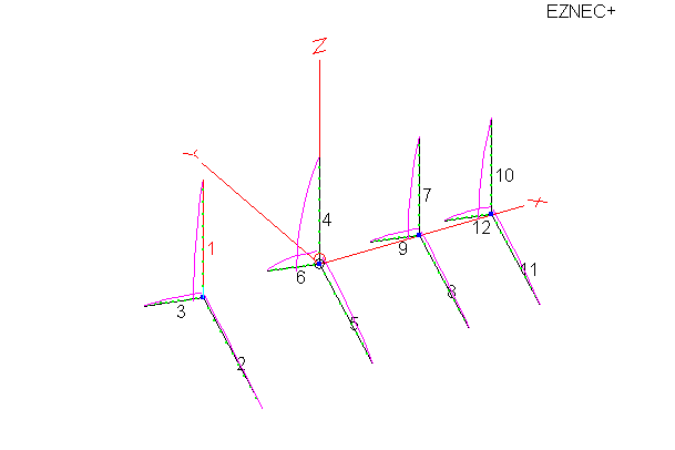
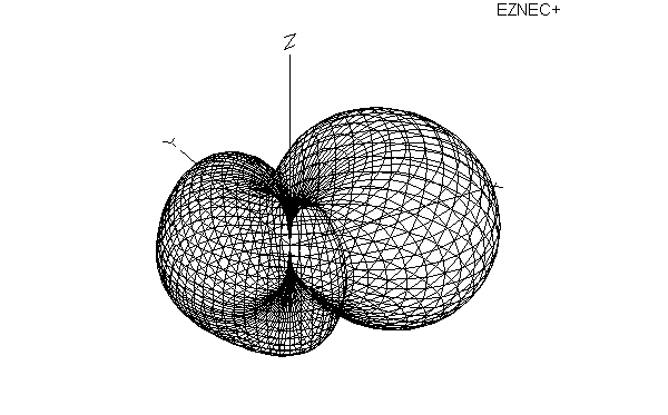
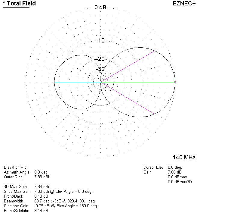
A couple of weeks ago I inquired with Tom Charles, the owner of Gizmotchy and Maco Antennas, about his 2 meter, 4 element Gizmotchy beam. The Gizmotchy is interesting to me because it has the ability to be used either with vertical or horizontal polarization, or both (not at the same time) with the right setup. I told him I was interested in buying one for my own station and would probably end up writing a review on the antenna if I did so. I was was asking what test documentation he might already have for the antenna. He very graciously offered to send me an antenna for free to try out.
I received the antenna very quickly, but had to wait for the weather to clear up to start the assembly. I also had to gather a few other pieces of the antenna system necessary to use the Gizmotchy effectively. Weather in Southern California was nice this weekend, so I was able to make a little progress on getting the antenna up in the air.
Here is a pic of the antenna as it is delivered, once you take it out of the box:
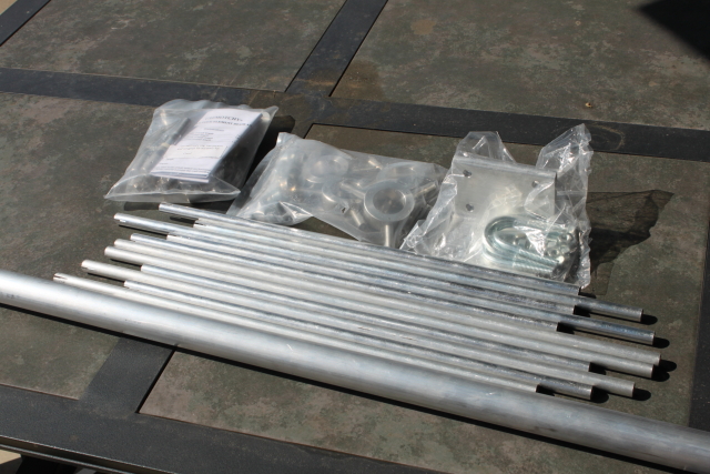
I don't know what gauge aluminum tubing is used, but I can tell you that it is heavy-duty for an antenna of this size.
This is a picture of the hub used to assemble the elements.
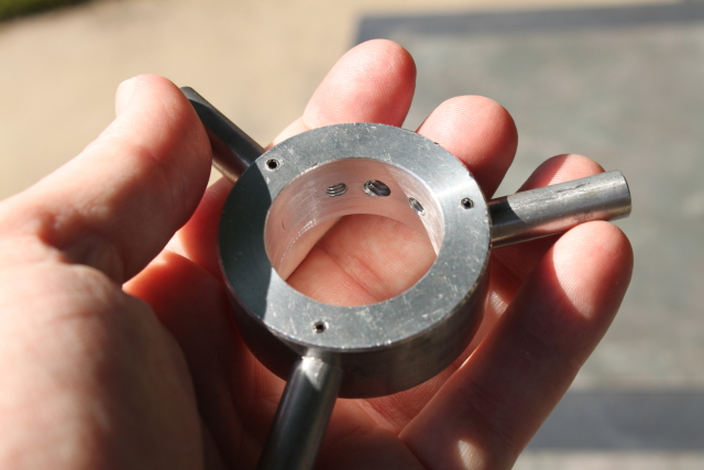
The mounts for the actual element pieces are solid aluminum and are attached to the center ring by pressing them into a drilled hole. They are then held into place by a roll pin that has been pressed in. The inside of the hub looks like it is then machined for a perfect, smooth fit. The hub shown in the above picture is for the driven element; it is the only one with additional tapped machine screw holes.
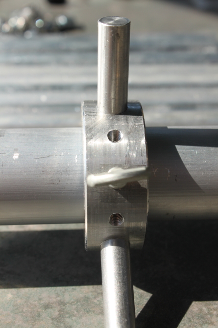
The hubs are slid over the boom and held into place by thumb screws. Here is a picture of a the mounted driven element hub:
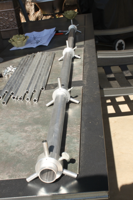
This picture shows the boom with all of the hubs assembled:
This is a good place for my first improvement suggestion for this antenna. The manual gives you the spacing measurements for the elements. You must measure and place them yourself, which is no big deal. However, since there is no need to adjust the spacing, it would be very helpful if the boom was already marked for you. But I'll take it one step better than that: Later on in the installation, you are going to want to make sure that all of the elements are aligned as straight as possible. However, when tightening the thumb screws on the hubs, it causes the whole element to turn slightly. If the boom was pre-drilled and tapped for the thumb screws on the hubs, the user would not have to measure, and they also wouldn't have to align the orientation of the elements manually. A pre-drilled and tapped boom would also make the the element assembly even stronger. I would think that this improvement would be simple to implement and add very little cost to the manufacturing process, but it would be a huge win for the consumer.
As I mentioned before, the Gizmotchy antenna is interesting because it can be used with vertical or horizontal polarization. This dual purpose polarization is achieved by two gamma matches.
These are the main gamma match stubs for each section. The one with the plug is for the vertical elements to keep the water out. The hose clamps make them adjustable for tuning.
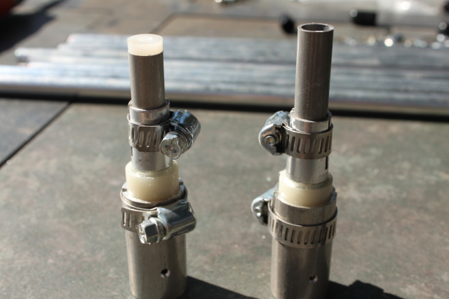
Here are the gamma match tuning sections fully assembled:
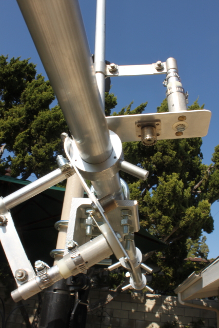
Notice that there are two SO-239 connectors. If you want to use the antenna for both vertical or horizontal polarization, you must use two feed lines to the antenna. In this picture, you see the boom and driven elements mostly assembled. However, this is where I ran into my first problem: Notice the L bracket in the picture that attaches the boom to the mast. Well, I couldn't mount the U-bolts to this L-bracket as it was delivered from the factory because the holes in the bracket didn't align with the U-Bolts. I couldn't get any of the U-Bolts for the boom or mast through the mounting holes in this bracket because the holes in the bracket were narrower than the U-Bolts. I used a rat tail file on the holes to widen them and make it possible to mount U-Bolts in the boom and mast bracket holes.
Here is a close-up picture of the assembled, not-tuned gamma match:
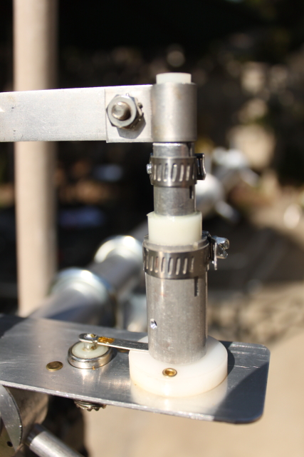
It should be noted that the gamma match assemblies do not come pre-measured for best match. I wanted to see where they were out of the box, so I just attached everything together for some measurements down the road. This is also where I encountered my second problem with the antenna assembly: The package was missing one of the small bolts necessary to assemble one of the gamma matches. When you open each of the bags of parts, you'll see a sticker indicating that the bag has been weighed for accuracy. Well, the hardware bag that I received was short one bolt but had one extra nut, which is probably why it weighed out OK. It wasn't a big deal because I had some extra hardware that kept the antenna assembly going.
While I was looking through my bin of nuts and bolts for compatible parts, I decided to give one of the supplied Gizmotchy antenna machine screws a magnet test to verify that it was stainless steel. To my surprise, I found that it was not stainless steel (stainless steel is not magnetic). The supplied machine screws and nuts have a finish that makes them appear to be stainless; they're better than nickel plated, but they're not stainless. I hope they hold up to the weather.
Here is the antenna fully assembled, ready for tuning and testing:
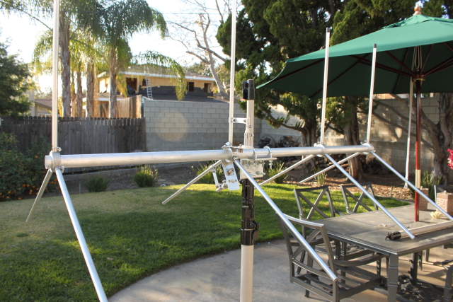
In this picture, I've already aligned all of the elements. There is probably an easier way, but I accomplished this by having a helping hand hold a straight edge up along all of the vertical elements. I then rotated each of them until they were square against the straight edge. As you can see from this pic, the boom is really very sturdy for an antenna of this size. In fact, the large boom diameter is really unnecessary and just adds extra weight. However, I'm sure that Gizmotchy uses the same boom and element hubs for more than one antenna design, so I'm sure it helps keep the costs down, which is perfectly acceptable to me.
I have one last observation about the assembly before I move on to tuning and testing. Each of the element's radials are attached to the hub by a small hose clamp. After tightening the clamps, the fit is good although there can be a little play on each rod, which isn't a big deal. The package comes with small sheet metal screws, one for each of the radials. The instructions do not indicate what these are to be used for, but if you look carefully at the the assembly diagrams, you can see that they are to be used as an augmentation to the hose clamps to secure the radial to the element hub. however, none of the aluminum parts are drilled and tapped for these screws. There is no possible way that anyone can drive one of these small sheet metal screws into the aluminum rod without it being pre-drilled and tapped for assembly. I tried to attach one screw without success, then tried to hand drill it, and then quickly realized that the only way to accomplish this would be to use a drill press. For this 2 meter antenna, the additional locking screws are completely unnecessary, so I scrapped the idea. I hope their bigger antennas have the element radials drilled and tapped from the factory.
Next, I'll talk about tuning and then finish mounting the antenna for use. I also have some factory test materials to share. Stay tuned...
I received the antenna very quickly, but had to wait for the weather to clear up to start the assembly. I also had to gather a few other pieces of the antenna system necessary to use the Gizmotchy effectively. Weather in Southern California was nice this weekend, so I was able to make a little progress on getting the antenna up in the air.
Here is a pic of the antenna as it is delivered, once you take it out of the box:

I don't know what gauge aluminum tubing is used, but I can tell you that it is heavy-duty for an antenna of this size.
This is a picture of the hub used to assemble the elements.

The mounts for the actual element pieces are solid aluminum and are attached to the center ring by pressing them into a drilled hole. They are then held into place by a roll pin that has been pressed in. The inside of the hub looks like it is then machined for a perfect, smooth fit. The hub shown in the above picture is for the driven element; it is the only one with additional tapped machine screw holes.
The hubs are slid over the boom and held into place by thumb screws. Here is a picture of a the mounted driven element hub:

This picture shows the boom with all of the hubs assembled:

This is a good place for my first improvement suggestion for this antenna. The manual gives you the spacing measurements for the elements. You must measure and place them yourself, which is no big deal. However, since there is no need to adjust the spacing, it would be very helpful if the boom was already marked for you. But I'll take it one step better than that: Later on in the installation, you are going to want to make sure that all of the elements are aligned as straight as possible. However, when tightening the thumb screws on the hubs, it causes the whole element to turn slightly. If the boom was pre-drilled and tapped for the thumb screws on the hubs, the user would not have to measure, and they also wouldn't have to align the orientation of the elements manually. A pre-drilled and tapped boom would also make the the element assembly even stronger. I would think that this improvement would be simple to implement and add very little cost to the manufacturing process, but it would be a huge win for the consumer.
As I mentioned before, the Gizmotchy antenna is interesting because it can be used with vertical or horizontal polarization. This dual purpose polarization is achieved by two gamma matches.
These are the main gamma match stubs for each section. The one with the plug is for the vertical elements to keep the water out. The hose clamps make them adjustable for tuning.

Here are the gamma match tuning sections fully assembled:

Notice that there are two SO-239 connectors. If you want to use the antenna for both vertical or horizontal polarization, you must use two feed lines to the antenna. In this picture, you see the boom and driven elements mostly assembled. However, this is where I ran into my first problem: Notice the L bracket in the picture that attaches the boom to the mast. Well, I couldn't mount the U-bolts to this L-bracket as it was delivered from the factory because the holes in the bracket didn't align with the U-Bolts. I couldn't get any of the U-Bolts for the boom or mast through the mounting holes in this bracket because the holes in the bracket were narrower than the U-Bolts. I used a rat tail file on the holes to widen them and make it possible to mount U-Bolts in the boom and mast bracket holes.
Here is a close-up picture of the assembled, not-tuned gamma match:

It should be noted that the gamma match assemblies do not come pre-measured for best match. I wanted to see where they were out of the box, so I just attached everything together for some measurements down the road. This is also where I encountered my second problem with the antenna assembly: The package was missing one of the small bolts necessary to assemble one of the gamma matches. When you open each of the bags of parts, you'll see a sticker indicating that the bag has been weighed for accuracy. Well, the hardware bag that I received was short one bolt but had one extra nut, which is probably why it weighed out OK. It wasn't a big deal because I had some extra hardware that kept the antenna assembly going.
While I was looking through my bin of nuts and bolts for compatible parts, I decided to give one of the supplied Gizmotchy antenna machine screws a magnet test to verify that it was stainless steel. To my surprise, I found that it was not stainless steel (stainless steel is not magnetic). The supplied machine screws and nuts have a finish that makes them appear to be stainless; they're better than nickel plated, but they're not stainless. I hope they hold up to the weather.
Here is the antenna fully assembled, ready for tuning and testing:

In this picture, I've already aligned all of the elements. There is probably an easier way, but I accomplished this by having a helping hand hold a straight edge up along all of the vertical elements. I then rotated each of them until they were square against the straight edge. As you can see from this pic, the boom is really very sturdy for an antenna of this size. In fact, the large boom diameter is really unnecessary and just adds extra weight. However, I'm sure that Gizmotchy uses the same boom and element hubs for more than one antenna design, so I'm sure it helps keep the costs down, which is perfectly acceptable to me.
I have one last observation about the assembly before I move on to tuning and testing. Each of the element's radials are attached to the hub by a small hose clamp. After tightening the clamps, the fit is good although there can be a little play on each rod, which isn't a big deal. The package comes with small sheet metal screws, one for each of the radials. The instructions do not indicate what these are to be used for, but if you look carefully at the the assembly diagrams, you can see that they are to be used as an augmentation to the hose clamps to secure the radial to the element hub. however, none of the aluminum parts are drilled and tapped for these screws. There is no possible way that anyone can drive one of these small sheet metal screws into the aluminum rod without it being pre-drilled and tapped for assembly. I tried to attach one screw without success, then tried to hand drill it, and then quickly realized that the only way to accomplish this would be to use a drill press. For this 2 meter antenna, the additional locking screws are completely unnecessary, so I scrapped the idea. I hope their bigger antennas have the element radials drilled and tapped from the factory.
Next, I'll talk about tuning and then finish mounting the antenna for use. I also have some factory test materials to share. Stay tuned...

