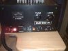
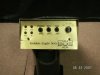
I recently acquired this amp and am facinated by it. I need some help though. Can someone tell me the history of how this amp fits in with the other kenrich models. It has a drive level on the front which points to a grid driven situation but the finals are grounded grid. I have never seen one set up like this one. Im interested in the history of this company. I have done research on the Maco line and some of the others. Does anyone have a timeline on when these were made in contrast to the others. The amp has 2 driving 6 20lf's. It seems to do about 1 grand, even has a cheezy modulation meter/ rf meter/ and cathode meter i cant seem to get to work. Any info on all of the above would be great. Love the grid driven amps like the pride/ wawasee modulators/ maybe the elkin?. Love the nostalgia. raider:sneaky2:

You are using an out of date browser. It may not display this or other websites correctly.
You should upgrade or use an alternative browser.
You should upgrade or use an alternative browser.
-
You can now help support WorldwideDX when you shop on Amazon at no additional cost to you! Simply follow this Shop on Amazon link first and a portion of any purchase is sent to WorldwideDX to help with site costs.
Golden Eagle 1k
- Thread starter Raider
- Start date
Golden Eagle made these back around mid 80 or so, the company was NOT related to Kenrich, nor Browning. these were made back when CB was still a huge thing, but on a decline. They also made a 750, and a 200 base, as well as a line of solid state mobile amps.
I doubt you will find much background on the builder, probably a fairly small operation, and fairly short lived. I owned a 750 and a 1K, they would both do well over the rated power output, but the build quality wasn't the greatest, I much preferred some of the other Sweep tube amps.
They were very impressive boxes while/when they worked.
Here are a few pics of others they built... going to hunt through some archived info i have and see what else I can dig up...
Attachments
i also have a golden eagle 1kw and im not sure if it is all orignal or if there has been some replacement parts mine does about 1300 with about 1/4 watt put into it im also interested in all i can learn about it any help would be apreciated.

I'm looking for somebody know how I can work on mines something is causing one of the tubes to go bad
If you need 20LF6 tubes for this amp, you can get the heavy duty European version at this link for $58 each: https://vacuumtubesinc.com/index.php/vacuum-tubes/new-tubes/20lf6.html
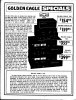
Now that is interesting. After reading their add, no one would ever buy the more expensive 1K model. The 750 weighs 9 pounds more (mostly transformer weight), with 500 watts more DC input power and with the exact same tube compliment, at $44.50 less...one more bit of info, a page I scanned a few years back, was originally a sale flier from H&Y
So it would eat tubes up faster. They were under $10 each when that amplifier came out.
Not for nothing but more than 36db of gain from two stages of sweep tubes cathode driven, is not possible. Is that 1/4 watt the deadkey drive level and the 1300 watts the full modulated output?i also have a golden eagle 1kw and im not sure if it is all orignal or if there has been some replacement parts mine does about 1300 with about 1/4 watt put into it im also interested in all i can learn about it any help would be apreciated.
Does anyone have an owner manual with operating instructions for a golden eagle 1K Just got one and would love to know the basics to tune it to a radio and any other info the owner manual has.
Thanks long night.
Thanks long night.
Does anyone have an owner manual with operating instructions for a golden eagle 1K Just got one and would love to know the basics to tune it to a radio and any other info the owner manual has.
Thanks long night.
https://www.worldwidedx.com/threads/how-to-tune-a-tube-amp.26225/
Would like to know if a golden eagle 1k comes up available let me know at mechanicbrian@gmail.com thanks folks
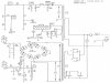
It has a drive level on the front which points to a grid driven situation but the finals are grounded grid. I have never seen one set up like this one.
Inspection of the schematic reveals the drive control is a mislabeled, screen voltage adjustment. Lowering the positive screen voltage on the tubes has a similar effect as increasing the negative bias voltage on the control grid and pushes the tubes closer to class C, rather than linear operation. Use on SSB with the "drive" control turned down, would show the nasty class C distortion, where AM would hide it and make the knob appear to function as a carrier control.
Inspection of that screen voltage supply shows some really bad design flaws. The load that a screen element places on the supply has some very unique characteristics. Did you know under hard drive conditions the screen can actually switch from placing any load on the supply and act like a source, by reversing the current flow and forcing it to flow backwards into the power supply? This condition is known as "Negative Screen Current" and is caused by secondary screen emissions, within the tube.
To stabilize the screen grid voltage in an amplifier like this, requires that the power supply have a very low internal impedance, in comparison to any load placed on it AND be able to "sink" any current the tube may be able to develop, if it's pushed into a condition where negative screen current occurs. Alternately, a shunt regulator can be added to the output of the screen supply to insure the most stable voltage under all operating conditions.
The Eagle tried everything from adding shunt resistance, to neon bulbs that ran completely over rated for the job. There is evidence the builder knew this flaw existed with two neon bulbs being placed in parallel. One burned up within the first 30 second high power key and two got it down the road, "just long enough".
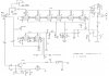
Because the neon bulb has such a small internal element surface area, it is unable to sustain more than a few milliamps of current. It was never intended for use as a voltage constant, like a VR tube with much larger cylindrical elements. It was designed as an indicator bulb. Although, the neon bulb could be pressed into VR service if the required current was miniscule and FAR less than these screens place on them.
Many sweep tube amps that use "Micky Mouse" methods to manipulate the screen voltage, suffer from unstable output that tends to increase, the longer the amp is keyed. Most often noticed in the AM carrier, that keeps creeping upwards until the tubes cool down and secondary emissions stop flowing.
When this happens, the screen voltage will actually be larger than the output of the supply they are connected to! That causes the DC bias current to rise and contributes to premature tube life. In most cases all of that "power drift", disappears as soon as you ground the screen, suppressor (beam deflection plates) and control grid, treat it like a triode and use simple cathode bias.
Reliable sweep tube circuits can be found in old "Amateur Radio Handbooks". One article in the 1980 handbook, outlines a "Quarter kilowatt from 6KD6 tubes".