Better Receive and Transmitting . . .
Haven't had a beam since I was on the CB in the 80's. When I did - it was a cheap copy of the PDL-2 quad beam. It was very nice and worked exceptionally well for a used antenna that I bought for less than $100. Since I've gotten back on the radio just two short years ago, I've run with the cheap but practical Imax 2000 with great results. Indeed; I've used it on 10, 12, 15, and 17 meter bands. As well as the CB band - of course. Made contacts all over the world when conditions were present. Still do. I felt the need to put up a beam to see how much better I could do than my vertical has done. I like to talk DX as often as the opportunity presents itself. If you like DX and have been considered putting up a beam, read on . . .
Mfr Claims and my Expectations . . .
As I wanted to get a horizontal beam, I really only considered two mfrs - Maco and Sirio. So I gave the Maco and Sirio beams both some serious scrutiny. The Maco was around 25 lbs and 17 ft in length, while the Sirio is only 12.5 lbs and only 13.5 ft long. The cost between the two -shipped- was $75; the Sirio is $139/$175 shipped, while the Maco is $208/$250 shipped. Purchased from Copper Electronics - BTW.
A 4 element beam has the advantage of a narrower beam angle compared to a 3 element beam. The advantages of horizontal polarized antenna over a vertical polarized antenna are less man-made noise in the receiver. Sirio claims that the SY 27-4 has a bandwidth of 600khz. Forward gain is also on the order of 11.5 dbd - another perk - if one believes in published specifications. So is having side and rear rejection of nearly 30 db/5 S-units. But if it all works as claimed by Sirio; that is another matter. I decided to go with the Sirio. Their international reputation and believable specs - as well as the cheaper cost - sealed the deal for me.
Construction/Materials
The beam arrived from Copper Electronics after one week via UPS. I quickly tore into the box and looked at all of the parts. The tubing is thin and very light. Had I lived in the Midwest, I probably wouldn't have bought the Sirio. We don't see ice storms nor sustained high winds where I live. Sunny California in the valleys are known for year-round mild weather. A Midwest ice storm would take out this Sirio beam in a New York minute. It might handle some decent wind; but ice is out of the question - IMO.
This beam is foolproof to construct. I imagine someone could do it wrong; but they would be hard-pressed to make a mistake. Sub-assemblies of all the radials, gamma match, and boom were made. The mounts for the radials are already measured and secured to the boom right out of the box. The boom comes in two sections, and aligning them together to keep the radials parallel on the two sections was done by placing them both on a flat floor and making certain that the radial mounts were all at the same point before joining together. Since it is just a slip-on fit with a tapered section on one boom half; I felt the need to keep these two halves aligned. So I simply drilled into the joint section and put a sheet metal screw in to cinch the deal. Sirio could and perhaps should have done the same. Not a major flaw by any means on their part; but an improvement to assure the foolproof assembly. Otherwise, it went together like clockwork.
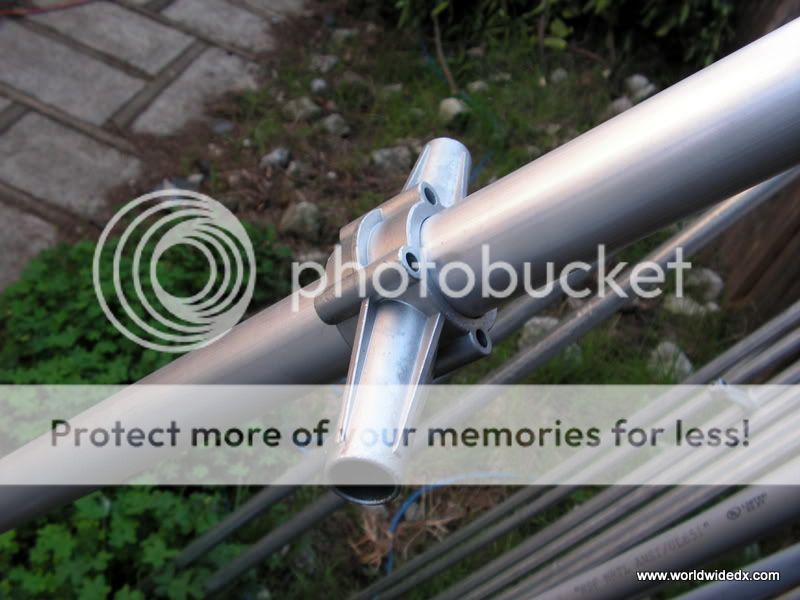
After the two boom sections were aligned and then tacked together with the sheet metal screw I provided, I then installed the mast bracket. It comes with four U-bolts for attaching the boom. As well as two larger U-bolts for securing the boom to the mast. It mounts directly at the center of the boom, and one must also be sure that it perpendicular to the radial mounts to keep the assembled beam horizontal.

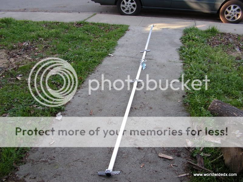
The radials are made of three different length section, all with tapered joints to connect the progressively narrower gage sections. There is a plastic sleeve provided for each joint; but I did not see the need for using them. As this would just add weight over its length and cause them sag when installed. There are two Phillips-head screws used to attach each section. Since the first two sections of each radial are all the same lengths; the end sections determine how long each radial will be. This made it foolproof. The gamma match section can be seen in the middle. The radials and the gamma match are held in place by recessed head Allen screws. It all went together both fast and easy.
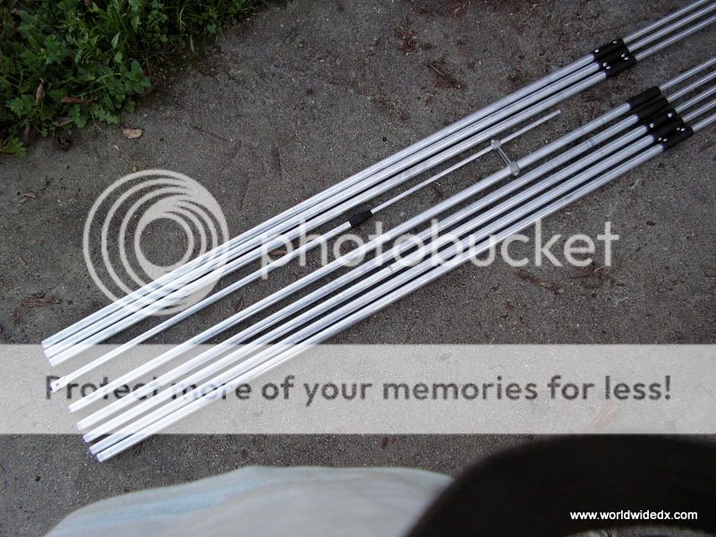
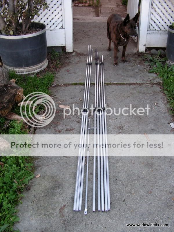
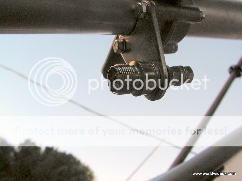
Here is the SO-239 connector on the boom. The gamma matching device mount to the screw and then to one of the drive radials. It is rated at 1000 watts for a short duration; but I never intended to use any more than 100 watts on the antenna. I'm sure that someone might be able to put a larger diameter gamma match on it to make it handle more current; but what does one expect from an antenna that cost less than $150? I doubt if I will ever put more than 500 watts in it sometime down the line.
After I assembled the antenna, I placed it on a 5 ft section of mast and placed it on the CDE/AR-22 rotor. Overkill on the rotor for this antenna, as it is a real featherweight beam. I also added a stainless steel loop on the upper 5 ft section - in order to use a piece of dacron rope to keep the installed beam level and free of sag. These parts didn't come with the beam, but I felt the need to make this effort to keep the beam as accurate as possible for best results. Took very little time and money for that mod.
I chose a 50 ft piece of RG-213 coax and installed it with some goop tape to keep the integrity of this connection from moisture. So I ran the beam up on the 36 ft push-up pole and checked the SWR. The factory lengths given for the gamma match and its attachment point on the driven radial was 5.4/SWR. I needed to bring it down and adjust the gamma match; but it was late and I decided to call it a night. I was very tired at this time and needed some supper . . .
I awoke the next morning and went out to begin work on the beam once again, when I realized that tragedy had struck overnight. Apparently, I forgot to tie it off with guy ropes, so the push-up pole buckled in the middle. The beam had come to rest itself in an apple tree, bent and crumpled. I then resigned myself to disassemble the entire beam and then painstakingly straightened out each section. There were no hard kinks, so it was fixable. This next time around - I will remember to use the guy ropes!
The job was done re-assembling it and I then set the beam on its reflector pointing upward, and then I adjusted the gamma match. The gamma match was slid inwards until I reached the lowest SWR that I could get out of it, and then the slider between the radial and gamma match was moved until the lowest figure was attained. I finally got a 1.1:1 match and ran it up to the roof and placed on the rotor once again. Checked the SWR once again; same measurements. The push-up pole also needed repair; it wasn't right yet. Not until I cut off a 4 ft section that was bent (see photo below) from the push-up pole; doing this made it straight and true once again. The beam itself is about ~30 ft from the ground surface.

Here is the finished beam pointing East this morning, Just after making some 5/9 contacts with Florida, Louisiana, Alabama, and Central Mexico. Skip conditions just opened up for a mere fifteen minutes - which was long enough to get some reports in. As one can see, it is as straight as it was when I took it out of the box. Sure was fun to build it and see some satisfying results. It was also a lot more work to do in order to give it a solid birth. The guy rope used is 3/16" dacron; and I used about 200 ft to secure it from four angles/90 degrees apart at two different heights along the mast.

Conclusions:
The bandwidth as given by Sirio was incorrect. They claimed its width is 600khz. On my MFJ-259B antenna analyzer, I saw a 2:1 VSWR of 1.8mhz. It works in the phone band of 10m up to 28.600mhz and all of the way down to 26.800mhz The X value is X=3 at its best point - at/around 27.500mhz. The back rejection is close to 30db - which is very nice. The beamwidth is also a little narrower than the 85 degrees; another added plus. I did send a note to Sirio to ask why I am seeing these readings, as opposed to their published specifications. I would suspect there is 'no free lunch' here. If it is getting such a wide bandwidth; then its gain must have been sacrificed.
Overall, I would say for the money spent and the quality of the workmanship/engineering of this antenna, I would give it a clear "5/9 rating". Clearly, Sirio had under-rated the specs. It is a fine performer and was a pleasure to assemble - IMO. Even if I had to do it twice.
Hope to talk to you the next time DX is in.
I'll be listening on the flat side . . .
Haven't had a beam since I was on the CB in the 80's. When I did - it was a cheap copy of the PDL-2 quad beam. It was very nice and worked exceptionally well for a used antenna that I bought for less than $100. Since I've gotten back on the radio just two short years ago, I've run with the cheap but practical Imax 2000 with great results. Indeed; I've used it on 10, 12, 15, and 17 meter bands. As well as the CB band - of course. Made contacts all over the world when conditions were present. Still do. I felt the need to put up a beam to see how much better I could do than my vertical has done. I like to talk DX as often as the opportunity presents itself. If you like DX and have been considered putting up a beam, read on . . .
Mfr Claims and my Expectations . . .
As I wanted to get a horizontal beam, I really only considered two mfrs - Maco and Sirio. So I gave the Maco and Sirio beams both some serious scrutiny. The Maco was around 25 lbs and 17 ft in length, while the Sirio is only 12.5 lbs and only 13.5 ft long. The cost between the two -shipped- was $75; the Sirio is $139/$175 shipped, while the Maco is $208/$250 shipped. Purchased from Copper Electronics - BTW.
A 4 element beam has the advantage of a narrower beam angle compared to a 3 element beam. The advantages of horizontal polarized antenna over a vertical polarized antenna are less man-made noise in the receiver. Sirio claims that the SY 27-4 has a bandwidth of 600khz. Forward gain is also on the order of 11.5 dbd - another perk - if one believes in published specifications. So is having side and rear rejection of nearly 30 db/5 S-units. But if it all works as claimed by Sirio; that is another matter. I decided to go with the Sirio. Their international reputation and believable specs - as well as the cheaper cost - sealed the deal for me.
Construction/Materials
The beam arrived from Copper Electronics after one week via UPS. I quickly tore into the box and looked at all of the parts. The tubing is thin and very light. Had I lived in the Midwest, I probably wouldn't have bought the Sirio. We don't see ice storms nor sustained high winds where I live. Sunny California in the valleys are known for year-round mild weather. A Midwest ice storm would take out this Sirio beam in a New York minute. It might handle some decent wind; but ice is out of the question - IMO.
This beam is foolproof to construct. I imagine someone could do it wrong; but they would be hard-pressed to make a mistake. Sub-assemblies of all the radials, gamma match, and boom were made. The mounts for the radials are already measured and secured to the boom right out of the box. The boom comes in two sections, and aligning them together to keep the radials parallel on the two sections was done by placing them both on a flat floor and making certain that the radial mounts were all at the same point before joining together. Since it is just a slip-on fit with a tapered section on one boom half; I felt the need to keep these two halves aligned. So I simply drilled into the joint section and put a sheet metal screw in to cinch the deal. Sirio could and perhaps should have done the same. Not a major flaw by any means on their part; but an improvement to assure the foolproof assembly. Otherwise, it went together like clockwork.

After the two boom sections were aligned and then tacked together with the sheet metal screw I provided, I then installed the mast bracket. It comes with four U-bolts for attaching the boom. As well as two larger U-bolts for securing the boom to the mast. It mounts directly at the center of the boom, and one must also be sure that it perpendicular to the radial mounts to keep the assembled beam horizontal.


The radials are made of three different length section, all with tapered joints to connect the progressively narrower gage sections. There is a plastic sleeve provided for each joint; but I did not see the need for using them. As this would just add weight over its length and cause them sag when installed. There are two Phillips-head screws used to attach each section. Since the first two sections of each radial are all the same lengths; the end sections determine how long each radial will be. This made it foolproof. The gamma match section can be seen in the middle. The radials and the gamma match are held in place by recessed head Allen screws. It all went together both fast and easy.


Here is the SO-239 connector on the boom. The gamma matching device mount to the screw and then to one of the drive radials. It is rated at 1000 watts for a short duration; but I never intended to use any more than 100 watts on the antenna. I'm sure that someone might be able to put a larger diameter gamma match on it to make it handle more current; but what does one expect from an antenna that cost less than $150? I doubt if I will ever put more than 500 watts in it sometime down the line.

After I assembled the antenna, I placed it on a 5 ft section of mast and placed it on the CDE/AR-22 rotor. Overkill on the rotor for this antenna, as it is a real featherweight beam. I also added a stainless steel loop on the upper 5 ft section - in order to use a piece of dacron rope to keep the installed beam level and free of sag. These parts didn't come with the beam, but I felt the need to make this effort to keep the beam as accurate as possible for best results. Took very little time and money for that mod.
I chose a 50 ft piece of RG-213 coax and installed it with some goop tape to keep the integrity of this connection from moisture. So I ran the beam up on the 36 ft push-up pole and checked the SWR. The factory lengths given for the gamma match and its attachment point on the driven radial was 5.4/SWR. I needed to bring it down and adjust the gamma match; but it was late and I decided to call it a night. I was very tired at this time and needed some supper . . .
I awoke the next morning and went out to begin work on the beam once again, when I realized that tragedy had struck overnight. Apparently, I forgot to tie it off with guy ropes, so the push-up pole buckled in the middle. The beam had come to rest itself in an apple tree, bent and crumpled. I then resigned myself to disassemble the entire beam and then painstakingly straightened out each section. There were no hard kinks, so it was fixable. This next time around - I will remember to use the guy ropes!
The job was done re-assembling it and I then set the beam on its reflector pointing upward, and then I adjusted the gamma match. The gamma match was slid inwards until I reached the lowest SWR that I could get out of it, and then the slider between the radial and gamma match was moved until the lowest figure was attained. I finally got a 1.1:1 match and ran it up to the roof and placed on the rotor once again. Checked the SWR once again; same measurements. The push-up pole also needed repair; it wasn't right yet. Not until I cut off a 4 ft section that was bent (see photo below) from the push-up pole; doing this made it straight and true once again. The beam itself is about ~30 ft from the ground surface.

Here is the finished beam pointing East this morning, Just after making some 5/9 contacts with Florida, Louisiana, Alabama, and Central Mexico. Skip conditions just opened up for a mere fifteen minutes - which was long enough to get some reports in. As one can see, it is as straight as it was when I took it out of the box. Sure was fun to build it and see some satisfying results. It was also a lot more work to do in order to give it a solid birth. The guy rope used is 3/16" dacron; and I used about 200 ft to secure it from four angles/90 degrees apart at two different heights along the mast.

Conclusions:
The bandwidth as given by Sirio was incorrect. They claimed its width is 600khz. On my MFJ-259B antenna analyzer, I saw a 2:1 VSWR of 1.8mhz. It works in the phone band of 10m up to 28.600mhz and all of the way down to 26.800mhz The X value is X=3 at its best point - at/around 27.500mhz. The back rejection is close to 30db - which is very nice. The beamwidth is also a little narrower than the 85 degrees; another added plus. I did send a note to Sirio to ask why I am seeing these readings, as opposed to their published specifications. I would suspect there is 'no free lunch' here. If it is getting such a wide bandwidth; then its gain must have been sacrificed.
Overall, I would say for the money spent and the quality of the workmanship/engineering of this antenna, I would give it a clear "5/9 rating". Clearly, Sirio had under-rated the specs. It is a fine performer and was a pleasure to assemble - IMO. Even if I had to do it twice.
Hope to talk to you the next time DX is in.
I'll be listening on the flat side . . .
Last edited:

