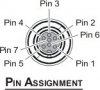
Here is the pinout information for the Yaesu VX-8r speaker/mic & gps connector on the top of the radio. The connector on the VX-8r is the same as the Yaesu FTM-10 series mobile radio. This means you can use the Yaesu CT-M11 cable to wire the connector to whatever you desire. This chart shows the pinout for the connector, the pin function, and the associated wire color for the CT-M11 cable.
<TABLE border=1><TBODY><TR><TH>Pin No.</TH><TH>CT-M11 Wire Color</TH><TH>VX-8 Series</TH></TR><TR><TD>1</TD><TD>Orange</TD><TD>MIC/PTT</TD></TR><TR><TD>2</TD><TD>Gray</TD><TD>3.3V</TD></TR><TR><TD>3</TD><TD>Brown</TD><TD>SP OUT</TD></TR><TR><TD>4</TD><TD>Green</TD><TD>GPS TXD (CONTROL)</TD></TR><TR><TD>5</TD><TD>Blue</TD><TD>GPS RXD (NMEA)</TD></TR>
<TR><TD>6</TD><TD>Red</TD><TD>GND</TD></TR><TR><TD>7</TD><TD>Black</TD><TD>SP SEL (CONTROL)</TD></TR>
</TBODY></TABLE>
The attached conenctor diagram is from the perspective of looking at the radio. If you put a 22K resistor between pins 7 and 2, the internal speaker will be disabled, which is probably what you need to do if you are going to use the cable for programming.