• You can now help support WorldwideDX when you shop on Amazon at no additional cost to you! Simply follow this Shop on Amazon link first and a portion of any purchase is sent to WorldwideDX to help with site costs.

2000 GTL unknown mod

Mar 22, 2018
11
1
13
53
Hello all, I'm hoping to find something out. I have a 2000 gtl and I'm trying to figure out what this is and why it is in here. I don't think it's factory. Any insight or ideas are greatly appreciated. 73's
 

Attachments

  • IMG_20240130_173533990.jpg
    IMG_20240130_173533990.jpg
    1.8 MB · Views: 16
  • IMG_20240130_173557118.jpg
    IMG_20240130_173557118.jpg
    859.9 KB · Views: 16
  • IMG_20240406_124425691~2.jpg
    IMG_20240406_124425691~2.jpg
    976.2 KB · Views: 16
  • IMG_20240406_123113870.jpg
    IMG_20240406_123113870.jpg
    1.4 MB · Views: 14

One thread is good enough, you didn't need to start another.

As I mentioned in the other thread, that's at L6, which is part of the filter before the first RX mixer. It looks like that mess lines up with the bottom edge of that shield on the back, and it almost looks like a lead hole on L6 is gouged out.

It is a transformer. That much is obvious. So half of your question is answered. It is most likely taking the place of L6, but why? I doubt anyone can say from a picture alone. Maybe L6 went bad, or maybe it was fine and simply not wide enough for a channel mod that was done. One thing is for sure, it probably receives more noise.

Does the radio work? Do you intend to put it back to stock? Is this just curiosity? It looks like there are a few empty holes in the back where parts used to be and maybe even a solder bridge or two as well. So suspect other mods too.

Maybe you can find a 148GTL or a TR-296GK for a replacement L6 (if it is even bad) and do a bit of trace repair where it was carved out around that leg, but something tells me that will only be just the beginning of the journey.
 
First off I apologize for being impatient and posting this twice. I'm still getting used to how this site works. Now the radio actually works quite well, the rx is not noisy at all, and it only has the channels it originally came with. As for mods the only one I know it had was an open clarifier which was removed. Other than that everything works as if it's a stock radio. So that leaves this transformer. I guess I'm mainly curious as to what it is, why it's there, and that equals what does it or did it do. I'm a firm believer in the fact that a person can learn something new every day and I do appreciate anyone who takes the time to share a little knowledge with me.
 
  • Like
Reactions: brandon7861
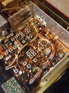
Cool. Then lets talk about those two transformers there.

Those two back to back transformers (L5 and L6) step up the impedance of the RX signal, couple between each other with a tiny capacitor, then steps the impedance back down. Inside L5 and L6, the larger windings have a capacitor in parallel with the inductor internally to form a resonant circuit, so instead of being broadband, they only pass a narrow band of frequencies. A capacitor naturally has a high Q since it has no resistive losses, so the Q of the overall tank circuit is mainly controlled by the Q of the inductor. Since the Q of an inductor is the inductive reactance divided by the ohmic resistance of the coil, the more turns it has (the more reactance) for a given wire diameter, the higher it's Q will be and the narrower the band of frequencies it will pass (when resonated with a capacitor). In order to take advantage of the high Q with a low source and load impedance, it has to step up the impedance in the middle where there are no low impedances to load down the tank and degrade the Q, hence two tuned transformers.

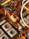
The reason I said it probably passes more noise is because, not only is that little toroid transformer unshielded allowing other signals to hop on it, I didn't see any parallel capacitor giving it a specific frequency response. Perhaps I was wrong about a parallel cap not being there, but if it's not, an untuned transformer is broadband and can pass a lot more stuff. So, when you have a 2kHz wide signal of interest and you have 5MHz of noise floor sneaking through, you get a worse signal to noise power ratio.

Edit: Another reason to really want that transformer shielded is because the next transistor, TR15, is a mixer, and if that toroid is picking up signals from the rest of the radio, they get mixed in where they shouldn't be.

L5 and L6.png
 
Last edited:

dxChat
Help Users
  • No one is chatting at the moment.