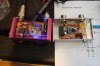
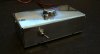
Hi there, I picked up an RM Italy KL-40 and was amazed at its simplicity.
Quick into: I have been in the electronics field for over 20 years and work in medical instrumentation/ xray. I build SS and tube audio amplifiers from scratch, as I find it fun and intriguing. I understand that building things sometimes cost more than new, but I like building. I am new to RF so just looking for some insight.
Anyway, I took this amp design http://www.rmitaly.com/download/manuals/KL40-manual_rel_400.pdf and hand etched a pcb and built it.
Instead of the propitiatory FET, I used a TO-3 IRF-350. I figured the input impedance was similar to the IRF 520; which has been used in some Linear amps. Well it did not pass the carrier signal. So I scrapped it and rebuilt it on a proto board. Same thing, idle current at about 8mA, but no amplification.
Observations:
Inductors:
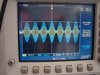
I crossed the metric magnet wire to an available 22 guage. I was only getting about 6volts peak (clean signal) at the gate Well, when I added 4 turns of 16 awg in parallel with the input coil (L1) I got 9 volts peak (distorted) and 200mA of conduction, but only about 700mV of gain. I have some 20 awg magnet wire on order.
Fet: If I increase the bias voltage I can make the fet conduct more. I added a voltage divider and increased idle to 12ma and have 700mA of draw when I key up. Still not transferring any gain to the signal. I tried a IRF520 in parallel but it only conducts (generates heat) but no signal gain. I have some MS1307's on order.
Also after adding the addidtional coil to the input of the fet I have a distorted signal.
So, have any of you made a 40w linear amp?
Did you use a BJT or FET?
Can someone explain what causes the signal to distort?
Is there an Ft for fets? What is the typical bandwidth of a power fet?
Lastly, I work with 27 mHz, I am using a 50 ohm dummy, and not transmitting. I am only doing this as an experiment so when I pass my tech test I can build other amps for use.
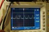
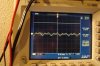
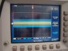
The first pic is the amp, the larger signal scope pic is at the gate of the fet, the smaller is the output.
Quick into: I have been in the electronics field for over 20 years and work in medical instrumentation/ xray. I build SS and tube audio amplifiers from scratch, as I find it fun and intriguing. I understand that building things sometimes cost more than new, but I like building. I am new to RF so just looking for some insight.
Anyway, I took this amp design http://www.rmitaly.com/download/manuals/KL40-manual_rel_400.pdf and hand etched a pcb and built it.
Instead of the propitiatory FET, I used a TO-3 IRF-350. I figured the input impedance was similar to the IRF 520; which has been used in some Linear amps. Well it did not pass the carrier signal. So I scrapped it and rebuilt it on a proto board. Same thing, idle current at about 8mA, but no amplification.
Observations:
Inductors:
I crossed the metric magnet wire to an available 22 guage. I was only getting about 6volts peak (clean signal) at the gate Well, when I added 4 turns of 16 awg in parallel with the input coil (L1) I got 9 volts peak (distorted) and 200mA of conduction, but only about 700mV of gain. I have some 20 awg magnet wire on order.
Fet: If I increase the bias voltage I can make the fet conduct more. I added a voltage divider and increased idle to 12ma and have 700mA of draw when I key up. Still not transferring any gain to the signal. I tried a IRF520 in parallel but it only conducts (generates heat) but no signal gain. I have some MS1307's on order.
Also after adding the addidtional coil to the input of the fet I have a distorted signal.
So, have any of you made a 40w linear amp?
Did you use a BJT or FET?
Can someone explain what causes the signal to distort?
Is there an Ft for fets? What is the typical bandwidth of a power fet?
Lastly, I work with 27 mHz, I am using a 50 ohm dummy, and not transmitting. I am only doing this as an experiment so when I pass my tech test I can build other amps for use.
The first pic is the amp, the larger signal scope pic is at the gate of the fet, the smaller is the output.