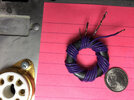
Been winding Baluns, tidying messy wires & tweaking this & that. Replaced the small core with 1-1/8" core (still mix 43). I'm focused on the RF Input section now. Changes take time to try and what works on a DL is not always good on an antenna.
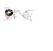
The attached "now" pic file is a diagram of the Input that is working best so far. Max drive is mid-20w's pep on 40. <12w pep on 10M. I'm not content with only 1 balanced output feeding the tubes. Feel like I'm wasting half my drive. I'm looking for some suggestions/criticism. Unfortunately, my test equipment is limited to an swr analyzer but I've come a long way. Input SWR is nearly perfect from 10-80 and the tank pi shows optimal settings in the mid-range of each component so I can fine tune. (Mr. Hacksaw removed some air cap plates) 40M PO is impressive, >kw pep easy with <30w drive.
To swap tubes I placed a toggle to switch Grid Bias and the multi-tap Screen Transformer has bullet connectors so I can swap secondary terminals from 350v or 400v. It's far from fast but do-able in about an hour. 10M performs the worst. If I short the tank coil & switch for just 10M, the PO goes up a lot, so it comes with multiband territory, I guess. These tubes are tougher than I expected. I made a few mistakes that did not yet destroy the tubes (leaving blower Off, etc). I need an Idiot Light for the Blower so that means...... IDK. I re-adjusted Buck-Boost for lower plate voltage & got a bit more usable plate current so progress continues just slow.
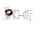
Back to RF Input, I'm trying to decide what circuit to try next. I think there's more efficiency to be had extract from the balun/swamped resistance arrangement. With one balanced lead going to RF ground I'm losing almost half the drive. the plan is to try connecting the other output ...... somehow. The other diagram is my next attempt as of now.
neil, NYC
The attached "now" pic file is a diagram of the Input that is working best so far. Max drive is mid-20w's pep on 40. <12w pep on 10M. I'm not content with only 1 balanced output feeding the tubes. Feel like I'm wasting half my drive. I'm looking for some suggestions/criticism. Unfortunately, my test equipment is limited to an swr analyzer but I've come a long way. Input SWR is nearly perfect from 10-80 and the tank pi shows optimal settings in the mid-range of each component so I can fine tune. (Mr. Hacksaw removed some air cap plates) 40M PO is impressive, >kw pep easy with <30w drive.
To swap tubes I placed a toggle to switch Grid Bias and the multi-tap Screen Transformer has bullet connectors so I can swap secondary terminals from 350v or 400v. It's far from fast but do-able in about an hour. 10M performs the worst. If I short the tank coil & switch for just 10M, the PO goes up a lot, so it comes with multiband territory, I guess. These tubes are tougher than I expected. I made a few mistakes that did not yet destroy the tubes (leaving blower Off, etc). I need an Idiot Light for the Blower so that means...... IDK. I re-adjusted Buck-Boost for lower plate voltage & got a bit more usable plate current so progress continues just slow.
Back to RF Input, I'm trying to decide what circuit to try next. I think there's more efficiency to be had extract from the balun/swamped resistance arrangement. With one balanced lead going to RF ground I'm losing almost half the drive. the plan is to try connecting the other output ...... somehow. The other diagram is my next attempt as of now.
neil, NYC