Ok, I picked a D201A and it had some funky stuff going on but after replacing a crystal, 3 trimmers and the meter IC it’s working but LSB & SSB are low power compared to AM. I want to do the Neutralization but the procedure mentions a T700 tuned for max DC (where is T700 and at what point is dc being measured) Also it says to adjust C706 (where is C706).
man is it me or are half of the Allignment produces wrong/ crystal labeled wrong in book?
Does anyone have a good neutralization procedure written they may care to share.
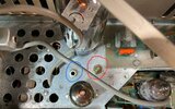
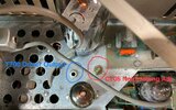
I included 2 pics with 5 adjustments I can’t even find reference too, I circled the adjustments????
man is it me or are half of the Allignment produces wrong/ crystal labeled wrong in book?
Does anyone have a good neutralization procedure written they may care to share.
I included 2 pics with 5 adjustments I can’t even find reference too, I circled the adjustments????