
D-44?/Cobra 148GTL/NPC mod?
Got this Cobra 148GTL that has the green bias wire clipped from the bias voltage supply junction and soldered to the cathode end of D-44.
Never seen the volting mod done like this on a 148GTL. The AM Limiter (TR24) has not been clipped out; nor has it been disabled from what I can see thus far. There is no 10mfd electrolytic cap on pin 9 of IC6 as one would do with the NPC mod either. Just doesn't make any sense.
The PEP output of the radio is about 20 watts. Trying to get it back down below stock output so that a local can put a 150 watt AB class amp on this thing. Even with the carrier turned down to 1 1/4 watts, it is still swinging to full output.
Anyone seen this mod before? is there another part of the board I should look at to see if there is any other part that may have been modified along with the D-44 mod? According to the schematic, the cathode of D-44/1N4003 attaches to the positive 13.8v input rail and the anode is attached to ground. Some kind of protection diode for the voltage regulator MB3756 I guess? Thing is, this isn't a 1N4003 diode in the D-44 spot. It looks like a 1N4148, or a 1N914, or something similar.
I want to put a 1N4003 diode back in D-44's place and put the green wire back on the bias junction so I can set the final bias, lower the PEP, and send this radio back on its way. But I don't want to overlook the un-obvious attempt at the NPC mod. Just looks like someone volted the final and nothing more. Anyone seen work like this before? Is there a sneaky freeky-deeky way to do an NPC mod without the usual spots used? Me thinks 'no'; but the radio says 'yes'.
J.J., ExitThirteen, AudioShockwav, Loosecannon?
This is an older 148 w/the 5 pin side mike.
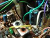
The green wire that has been clipped from the bias junction (in the center of this picture just above/right of the horizontal yellow wire) is attached to the cathode of D-44
Got this Cobra 148GTL that has the green bias wire clipped from the bias voltage supply junction and soldered to the cathode end of D-44.
Never seen the volting mod done like this on a 148GTL. The AM Limiter (TR24) has not been clipped out; nor has it been disabled from what I can see thus far. There is no 10mfd electrolytic cap on pin 9 of IC6 as one would do with the NPC mod either. Just doesn't make any sense.
The PEP output of the radio is about 20 watts. Trying to get it back down below stock output so that a local can put a 150 watt AB class amp on this thing. Even with the carrier turned down to 1 1/4 watts, it is still swinging to full output.
Anyone seen this mod before? is there another part of the board I should look at to see if there is any other part that may have been modified along with the D-44 mod? According to the schematic, the cathode of D-44/1N4003 attaches to the positive 13.8v input rail and the anode is attached to ground. Some kind of protection diode for the voltage regulator MB3756 I guess? Thing is, this isn't a 1N4003 diode in the D-44 spot. It looks like a 1N4148, or a 1N914, or something similar.
I want to put a 1N4003 diode back in D-44's place and put the green wire back on the bias junction so I can set the final bias, lower the PEP, and send this radio back on its way. But I don't want to overlook the un-obvious attempt at the NPC mod. Just looks like someone volted the final and nothing more. Anyone seen work like this before? Is there a sneaky freeky-deeky way to do an NPC mod without the usual spots used? Me thinks 'no'; but the radio says 'yes'.
J.J., ExitThirteen, AudioShockwav, Loosecannon?
This is an older 148 w/the 5 pin side mike.
The green wire that has been clipped from the bias junction (in the center of this picture just above/right of the horizontal yellow wire) is attached to the cathode of D-44
Attachments
Last edited: