
I recently purchased the KXV3a RX Antenna/IF Out/Transverter Interface board for my Elecraft K3. I have some plans for the station where this interface board will be desirable, but I'll save those for a future post. Follow along while I install the new board in the rig:
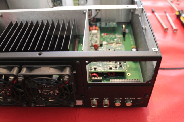
If you're adding this board to a completed rig (like me), the first thing you have to do is take the top and bottom covers off of the radio and remove the digital I/O board. I looked to see if there was a way around having to remove the I/O board, but it simply must be removed:
Next, you have to locate two jumpers labeled W1 and W2 on the board. They may be soldered on the pads, or in the case of newer builds like mine, inserted into the connector block right next to the W1 and W2 labels:
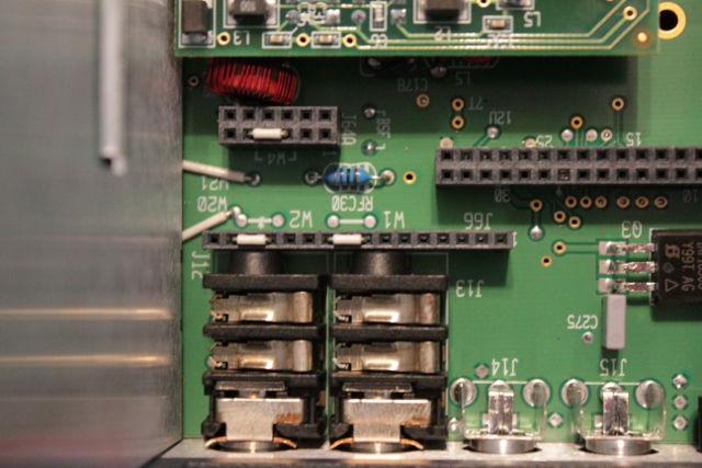
The jumpers in the middle of the picture above look like white wires inserted into the connection block. You have to remove those with some fine tipped needle nosed pliers.
Next, you prep the TMP cable, attach it to the KXV3a board and install the board, lining up the pins with the connection block. This sounds simpler than it actually is because the tolerances are very tight. You have to carefully position the board and gently align the pins before pressing it in place which takes a few minutes.
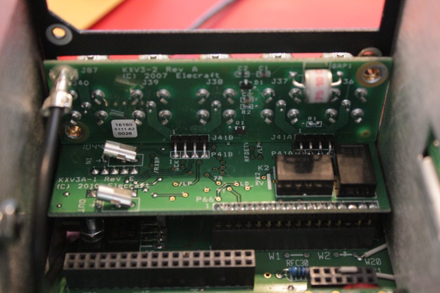
After that, you put the cover plate on, securing the board to the frame. The end result looks like this:
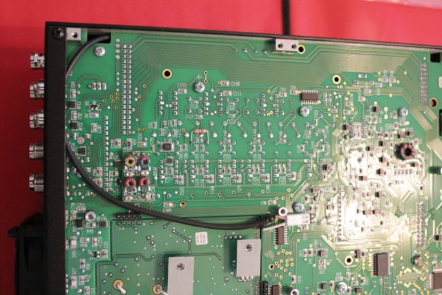
The TMP cable that you attached earlier is routed through the underside of the main RF deck and attached to the appropriate connector.
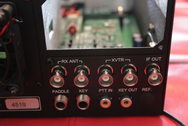
Reinstall the digital I/O board, put all the covers back on, and you end up with a rear panel that looks like this:
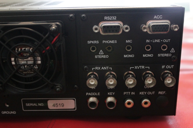
Lastly, you run a transceiver TX gain calibration using the K3 Utility software (which is automated) and you're done!
If you're adding this board to a completed rig (like me), the first thing you have to do is take the top and bottom covers off of the radio and remove the digital I/O board. I looked to see if there was a way around having to remove the I/O board, but it simply must be removed:
Next, you have to locate two jumpers labeled W1 and W2 on the board. They may be soldered on the pads, or in the case of newer builds like mine, inserted into the connector block right next to the W1 and W2 labels:
The jumpers in the middle of the picture above look like white wires inserted into the connection block. You have to remove those with some fine tipped needle nosed pliers.
Next, you prep the TMP cable, attach it to the KXV3a board and install the board, lining up the pins with the connection block. This sounds simpler than it actually is because the tolerances are very tight. You have to carefully position the board and gently align the pins before pressing it in place which takes a few minutes.
After that, you put the cover plate on, securing the board to the frame. The end result looks like this:
The TMP cable that you attached earlier is routed through the underside of the main RF deck and attached to the appropriate connector.
Reinstall the digital I/O board, put all the covers back on, and you end up with a rear panel that looks like this:
Lastly, you run a transceiver TX gain calibration using the K3 Utility software (which is automated) and you're done!
