• You can now help support WorldwideDX when you shop on Amazon at no additional cost to you! Simply follow this Shop on Amazon link first and a portion of any purchase is sent to WorldwideDX to help with site costs.

Avanti Sigma4: An alternative view point

eddie its not your communication its my lack of understanding of how current is represented in your nec plots,
im not sure what the nec current file shows without a pictoral representation to compare the numbers against,
for instance, on your model we know the current in the lower 1/4wave is out of phase with the upper 1/2wave and on the 5/8wave its out of phase in the lower 1/8 but i don't see anything to indicate that in the nec drawing,
is phase just displayed differently or not displayed in the drawings at all with only magnitude been displayed?

i started out playing with the nec demo trying to figure out how to model the sigma and got a lost in eznec4,
cebik made me realise that ezbob had several advantages i could make use of to get my ideas across,
it was free
simple user interface
its much faster than nec
the graphics are easier to understand ( for me )

i only see one downside, accuracy aint so good :D
 
eddie its not your communication its my lack of understanding of how current is represented in your nec plots, im not sure what the nec current file shows without a pictorial representation to compare the numbers against, for instance, on your model we know the current in the lower 1/4wave is out of phase with the upper 1/2wave and on the 5/8wave its out of phase in the lower 1/8 but i don't see anything to indicate that in the nec drawing, is phase just displayed differently or not displayed in the drawings at all with only magnitude been displayed?

i started out playing with the nec demo trying to figure out how to model the sigma and got a lost in eznec4, cebik made me realize that ezbob had several advantages i could make use of to get my ideas across, it was free simple user interface its much faster than nec the graphics are easier to understand ( for me )

i only see one downside, accuracy aint so good :D

I also see accuracy as a problem, for sure if we don't understand every aspect of the system...and I'll never reach that level. All I can do is speculate on what I think I know, what I hear, and what I think I understand about modeling...which is not much based on the depth of the subject.

In your remarks above that I highlited in red, I understand what you are talking about I think, and I don't know why my Antenna images show the currents in red to appear to be in-phase rather than out-of-phase...like we know it should be and as EzBob shows. I think this problem was what led to our questioning the phase we were seeing back when Henry and Dxer first posted. It is confusing. Did I get the drift of your question right?

How did Cebik provide you with visuals of a nec4 version of Exnec? Did he send you some Eznec reports when y'll talked? The only product I've knowingly ever seen of a more advanced version than my Eznec5 is Dxer's Eznec5+ models, and I think it shows a lot more in the graphics area, but I'm not aware of anything except the headers and the color differences shown on those reports and images that he posted. You will note on his postings that it shows in the top right hand corner...Eznec 5+.

Dxer told us he had his nec4 license coming, and I guess he was planning on purchasing Eznec Pro or > real soon. I understand that the nec4 license itself cost upward of $500, and then you have to pay Roy for his Eznec Pro interface to run the nec4 engine. I think that is the way it is...and I'm far from being that serious about modeling. I think this is why Roy cautions not to put too much faith in the graphic depictions in the Antenna View, and to refer to the tabular output noted as "Current Data". Does this make sense?

Do you still have something from a model maybe that Cebik showed you from a nec4 version, that would help demonstrate for me the differences you see when using a nec4 version of Eznec vs. using the nec2 versions? If not then do this for me: scan image in question into Paint, and add you marks for your significant issues, and email it to me like you do with EzBob. I'm not sure I'm getting a minds-eye picture of what you're describing. If you want me to mark up on one of my reports, something similar in Paint, let me know, OK. And, if I'm complete off track in understanding here, let me know that too.

The forums are a great way to exchange ideas, but the medium is severely lacking in any spontaneity.
 
Need the mast be grounded to earth, and how much mast should be connected to the antenna?

The mast does not need to be grounded and I see a slight increase in gain using a 1/2 wave mast. Although, no experimenting was done with different length masts.
 
cebik never showed me anything eddie, we corresponded via email, he talked about the pages of argument such antennas cause and that getting accurate results would be difficult, i thought about what he said and decided lb was pretty sharp with nec and antennas in general, if it was as simple as loading it into nec to get accurate results then there would not be any arguments over what it is and how it works,

i don't want you to change your plots, id just like to know if they are displaying phase or not, if they are then how?
if antenna view only shows current magnitude and you have to look at the phase data to determine phase theres no point in me trying to make sense of the plots with regards phase in antenna view, maybe thats what roy cautioned about,

it would be nice if phase was shown by color or which side of the element it is on but that may not be practical or even possible :unsure:
 
cebik never showed me anything eddie, we corresponded via email, he talked about the pages of argument such antennas cause and that getting accurate results would be difficult, i thought about what he said and decided lb was pretty sharp with nec and antennas in general, if it was as simple as loading it into nec to get accurate results then there would not be any arguments over what it is and how it works,

Bob, I didn't think Cebik sent you anything, but something you said earlier made me wonder...so I asked the question.

i don't want you to change your plots, id just like to know if they are displaying phase or not, if they are then how? if antenna view only shows current magnitude and you have to look at the phase data to determine phase theres no point in me trying to make sense of the plots with regards phase in antenna view, maybe thats what roy cautioned about,

You may be right Bob about the way Eznec displays the indicators for currents (the red lines). It has been my experience...when you create a model these red lines don't show up until you click on the Currents Tab, and then the tabular list of currents window opens up. So I figure this is the way Eznec turns currents on. I don't see a way to then turn the currents off again until maybe you create a new model.

I could be dead wrong, but IMO the lines that indicate the Eznec currents only give the viewer an idea of the magnitude of the currents and do not accurately display the phase relationships among the antenna segments...as the phase goes in or out. If I understand your EzBob idea, when the phase changes, you will see the current line cross the centerline of the element, right and maybe even see the color change if the phases are opposite, Right?

it would be nice if phase was shown by color or which side of the element it is on but that may not be practical or even possible :unsure:

I tried the color thing and all it does is change the color of the current lines displayed, there is no color control relative to the phase. If Eznec did so, then that would eliminate a lot of questions in this regard. If I can construct a good question about this idea, then I'll email Roy and ask.

A thought comes to mind for a question. Do you recall W8JI displaying a worst case scenario for the Imax? Do you recall how the current on the radiator appeared to repeat the same exact pattern all the way down the same side of the mast to Earth?

Questions are:
is that depiction possible?
did that display raise a question in your mind?
how would Ezbob display that situation?

Maybe this whole question we have in our minds about the displaying of currents is not important or impractical to these guys that develop such software and work with modeling all the time.
 
eddie, i would say the current situation m8ji shows is more than possible,
if i wanted to portray the same info and make it easier to visualise with ezbob id do it like this, im not saying its the correct way but it is easier to visualise the concept.

imaxi.png
 
Perhaps this model of the Vector in CST Microwave Studio will help explain the radiation currents from the antenna. They are shown in color, phase, and magnitude. The currents on the radials are lower individually but remember the current is divided into four radials. This model is the work of Mr. Lorenzo, one of the engineers at Sirio.

It is much easier to understand why Cebik referred to the antenna as a non-apparent collinear. One can see how the unconstructive radiation is confined within the cone while the cone emits it's own beneficial radiation. This in not the conventional collinear however, it does produce the same effects based on the same theory.
 

Attachments

  • Coaxial J-Pole in CST.jpg
    Coaxial J-Pole in CST.jpg
    42.9 KB · Views: 29
Last edited:
how can anybody argue that is a simple j-pole ?

"none aparent colinear array" (y)

you have to love the little secondary lobes forming above the radials, i wonder if the adjustments i make change the secondary lobe size, maybe thats a bit of horizontal from the hoop, looks kind of doughnut shaped

the currents flow like ezbob predicted
currentsinsigma4-1.jpg


shockwave i thank you.
 
Last edited:
eddie, i would say the current situation m8ji shows is more than possible, if i wanted to portray the same info and make it easier to visualise with ezbob id do it like this, im not saying its the correct way but it is easier to visualise the concept.

imaxi.png

Bob, that is the way I imagine 2 wavelengths of current distribution, magnitude, and phase to appear. I also think it is considered good science that the bottom 1/8 wave portion in the 5/8 wave radiator, is noted to be out of phase with the top 1/2 wave, and for example would not effectively add to the radiation of an Imax, correct?

If my comments above are true, then I also think this might mean that the energy from the bottom 1/8 wave is offset or canceled by an adjacent 1/8 wave portion right above that is said to be...out of phase, correct?.

And if this is so, then I assume that the recipocal response of TX/RX has to also apply, correct?

So, does this ultimately mean that a full 1/4 wavelength of a 5/8 wave radiator is considered somewhat or fully void of emitting or receiving any effective radiation. Thus the only advantage to be noted in using such a radiator length is to physically raise the radiating element a few feet higher than say a similar end fed 1/2 wave being compared with the feed points at the same height?

I'll also note that your EzBob model above confirms your point the other day...about a portion of the mast below the vertical antenna being out of phase with the antenna and I tend to agree. Therefore I can't explain how Shockwave and I both can produce models that show the mast below the radiator to be both in-phase and out, or at least appear to be so. Again, my understanding about these modeled currents and phase may well be skewed.

I was able to get my Sigma 4 model to conform to the EzBob idea, but while doing so I noticed that nearly everything I did to the antenna, during that process, affected the currents and their phase...one way and then the other.

So, two things occur to my thinking regarding the currents issue.
1) I still don't understand currents and phase.
2) I can't tell when I'm looking at a good model vs. bad.

I guess it could be concluded Bob, that when you noticed the sweet spot during your tuning of the Vector styled antenna, maybe these currents were shifting about as I note above with my models. I would think maybe you're right and this collinear affect that Cebik and you refer to...might just be an (on-again/off-again) kind of deal with this styled antenna.

Do you recall what drove you to persue this idea of adding length, or was it just a lark that you noticed while adding length in small steps? Adding several feet to the Vector trying to see what happens would seem dubious to me? Most CB antennas that I'm fimiliar with don't even provide enough additional material to do such experiments. The Sigma 4 is pretty much that way, and IMP it is set and forget construction. Based on my reading of the manual I think the tuning was also originally meant to be along those same lines, set to the indentions provided and your done.

Right now, I'm in a rush to try and beat CDX007 in getting another of my antennas in the air to compare to my New Gain Master. I challenged him to press on with his report, but maybe I should have waited. I'm considering putting my Sigma4 up against the Gain Master like Shockwave did.

First though I want to switch my AP vs. GM and see how the signal reports I've been taking compare. Maybe that will settle some of the doubts about using a switch box. I don't say this to mean doing so is the best way, but my having the ability to switch between antennas rapidly does have its advantages in many ways using you on-air perceptions about audio quality and strength of signal and other factors you might miss while taking time to change antennas on the same install. If I can rule out some of the material issues associated with comparing antennas using different coax and location...them maybe the results will be a bit more reliable. I'll be very surprised however if this switch fails and doesn't show similar results.

007, I've getting a head of steam worked up. (y)
 
Last edited:
a no radial 5/8wave endfed on a mast with total height 2 wavelengths is what i intended to illustrate eddie, i guess my drawings sometimes get the message across lol;)

i have no idea about what the lower 1/8wave of a 5/8wave does in the far field with regards cancelling radiation from the 1/8wave of radiator above it above it, i saw it posted recently, its not something i have looked at,

i will use this analogy to explain why,

you go to a christmas party, there are two large cakes on a table,
plenty of folk are happily tucking into the first cake while only a handfull take the second cake,
you think "everybody is eating that one, must be the best ill try it", you take a bite and it tastes like shit, you go to the second cake,
the second is hmmmmm hmmmm the best cake you ever tasted and you like baking,,
you don't ask for the recipe for first cake,


eddie, i don't see how you made models that showed the currents to change phase, how they are presented when you turn things off and on in nec may not fit what you expect or how you expect them to be presented, i did not even use the same method of presenting my currents in all my drawings but in my minds eye i was portraying the same thing,
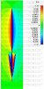
the cst plot is just another much more detailed way to display the same data,

the cst microwave studio plot posted thanks to shockwave and mr lorenzo at sirio is the best i have seen by far,
no plot has ever given me so much pleasure :D


changing the relative lengths adding hoops ect, will shift phase relationships to some degree, thats plain physics,
one theory ( from a forum member ) is that extra gain comes from the increased separation of current maximas which extending the sigma does,

how i think that could be effecting the farfield is speculation from me ( remember cebik did not fall off his chair laughing, he said it was perfectly possible )
i first observed what the sigma could do, argued with everyman and his j-pole, explained it to mr cebik, got the answer i had hoped for and went looking for his illusive "none aparent colinear array" that could be formed by folding radials up towards the radiator and caused pages of meaningless arguments from people who did not understand how they worked, ( his words not mine ) ,
the only antenna i could find that fit how claimed the sigma worked was the open sleeve and its derivitives,
look at the plot and read the open sleeve article in the arrl, all will become clear,
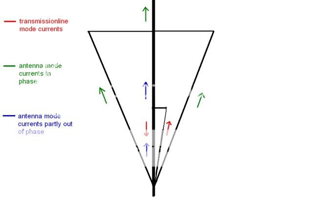
ezbob also shows the contraflowing transmissionline currents in the gamma section, they are there too,

yes the plot shockwave kindly posted shows that the antenna mode currents are where ezbob predicted and the radiation from the sleeve is in phase with the upper 1/2wave very much like a modified OPEN SLEEVE MONOPOLE,
there is no more arguing about what the sigma4 is for me, its taken 6 years im a patient guy,
if anybody wants to argue with j-pole/endfed 1/2wave nonesense it won't be with me:headbang, im sticking with the folk that understand antennas,

i don't recall exactly when i realised that i could tune a sigma better than my buddies, probably around the time they started asking me to come help tune theirs, remeber your tuning settings are no good for our cb band, i saw with my own eyes that many settings would provide a good vswr but some worked better than others,
i don't see anything odd about modifying anything, i mod everything not just radio related stuff, whats odd to me is thinking you can't make anything better,


good luck in your tests with the gainmaster, we are still awaiting delivery, i would like to see your test against your stock sigma at your location,
when i tested on two poles in the field id swap them around and try to average the results out, you know my feelings on veracity two antenna tests but so long as you enjoy what you do its all good to me,

the gm had and probably still has its detractors, the "its just a wire dipole in a tube" brigade, these guys learned radio from the same book as "its just a j-pole" camp,
i won't knock it before i try it, shockwaves test gives me reason to believe there could be something to it,
there is more than one way to beat a 5/8wave groundplane and this could possibly be another method,
those who think "inside the box" are forever stuck "inside the box",

i hope the gainmaster does what is claimed, that opens up new homebrew avenues(y)

take it easy eddie.
 
Last edited:
Shockwave;243422 11/22/10 said:
Bob, Sirio used CST to model the antenna. As I've mentioned before it is their engineers who told me about the mast radiation with the Vector and the 5/8 wave. They are claiming the section of the mast under the Vector is in phase with the main radiator. I can absolutely confirm the antenna has more far field gain when connected to the mast. The difference is slight but it can be measured.

Shockwave, in your claim above...are you talking about your real world comparisons or an Eznec model. I see the same increase in gain whenever I add a mast with my Eznec models, and I always see a drop in gain when I isolate the mast...even by a few inches or eliminate it from the model all-together.

Also, if this is not off the subject. My Eznec models for a conventional 5/8 wave GP antenna with a mast always show the current magnitude values on the mast to be significant, while the same mast currents on the Vector/Sigma4 models show to be insignificant in values. I'm not referring to the "Antenna View" of the current magnitudes here either.

I may be way off on my understanding of these currents and for sure how phase is involved, but that is what I see when I compare the tabular list of currents for both.
 
In my conversations with Mr. Lorenzo it was clear his model of the Vector is showing the radiation currents that descend on the mast to be beneficial to gain. The CST model shows a small section of mast under the antenna. While the magnitude is low, the phase is beneficial as noted by the color. I then set up some equipment on my test range and measured a slight improvement in signal with the antenna attached to the mast. The fact you are seeing higher mast currents on the 5/8 wave ground plane is not surprising. Keep in mind these currents on the mast and lower portion of the radiator are deconstructive to gain on the typical 5/8 wave ground plane.

I can also relate to the patience Bob85 has had with fully understanding the Sigma / Vector design. It has been a frustrating battle for many who have tried to understand this powerful antenna including myself. I always knew it worked way better then a J-Pole and noticeably better then a 5/8 wave ground plane. Understanding exactly why took the help of Mr. Lorenzo at Sirio. The picture formed by their CST modeling software goes well beyond what one could sum up in a thousand words. The staff at Sirio have gone above and beyond the normal expectation of customer service countless times that I know of. Surprisingly this level of service is offered to everyone from their big distributors right down to the single customer just trying to make the right purchase.
 
maybe im not looking at the bottom of the cst plot right, it looks like a freespace plot,
to me it shows currents stop at the hub but the radiation field extends slightly beyond the hub in the same way the magnetic field of a magnet extends beyond the physical end of the magnet,

i am waiting for tube to arrive from dxengineering, i will test the isolated vs none isolated idea to see if i get the same results as shockwave does on his fm broadcast band antennas;)
 
If it were just the field extending below the hub and not actual mast radiation, I think the plot would look more like the magnetic flux lines of a magnet. Meaning they would be bowed downwards rather then maintaining the same angle along the mast. The way I see it is the radiation is continuing along the mast at a decreasing magnitude. We no longer see colors of red and deep blue. We do see yellow and sky blue in the same phase and shape as the currents above, just with less magnitude.
 

dxChat
Help Users
  • No one is chatting at the moment.