Is common mode even an issue on UHF though?
For the t2lt antenna design he is looking at? I would say yes.
The DB

Is common mode even an issue on UHF though?
Similarly not being an amateur and having no interest in the very expensive 934 Mhz we had back in the 80's which was barely affordable and lacking equipment for amateurs was never going to be cheap in the 80's.
The ones I have seen used have had tighter windings than your average top end of hf ones, but intuition tells me not tight enough and far far too many turns, I have obviously considered clip on ferrites as an alternative, I plan using a cushcraft ARX 450 for the job as with a great lump of basalt volacanic plug blocking my main target area and a quarry blocking me to Glasgow my home town, supplied handi antenna and upgraded na771 just don't cut it from indoors,
I have to walk to river front to get round both, I have made the trip from there but even then signal is touchy and just turning round or moving slightly can destroy signal, I generally listen for best incoming signal and obviously that will be reciprocated on the outgoing side, not sure if I can access roof of 3 storey building, but do have a satellite dish outside I don't use and could fit the Ringo Ranger there, but although I know its not ideal may be only option, I'm also aware RG213/U isn't the best option at that frequency either,
Hardline heliax with N plug would be a far better solution but very costly and even then I might still not achieve my objective, might not even be achievable from chimney or 10 foot mast on top of it, its more for curiosity than anything else,
I realise the bend ratio may not be achievable with any coax and line isolater / ferrite clip ons may be a far more productive solution as common mode current will almost definately be a certainty with that antenna, I really do need to get a vna or mini vna that can go that high or at very least an antenna analyser, I know mfj 269 will go there but it ain't gonna be most accurate tool for the job, although might be only semi affordable one, It could also be used for building an efficient T2LT as well, so it could come in useful to many people operating up there, even a swr meter for that frequency range is pretty expensive, I really just wanted confirmed my suspicion that the chokes I've seen used which resemble that on the gainmaster are not effective for the job, thanks for taking the time to answer me, I would imagine dimensions wouldn't be too far off a similar one for the amateur 70cm's band but have struggled to seek info even on that, I'm thinking same as you ferrite clip on/s is deffo way to go but was curious if it was possible with coax,
it is just a gut instinct from what I know about HF chokes that what I have seen just can't be effective as those types of chokes are very narrow banded and without sufficient choke impedance could either be useless at best and detrimental at worst.
Thanks for your effort, it is much appreciated, Jazz 73.
George, you can usually find lengths of second hand hard line heliax at radio rallies and its all perfectly usable. A friend of mine has accumulated quite a lot of quite decent lengths over the years, all with those big fat expensive N-type connectors on the end.
As for the chokes I think you're basically going to be bifilar winding on a suitable mix ferrite core whatever that mix would be. Is common mode even an issue on UHF though?
") 73 Jazz
73 JazzI've done some research on-line on these, and there really isn't much in the way of straight forward information. Typically they say anywhere from 4 to 6 turns without a form size.
Of the few that do give coil diameter sizes most say to use a 4 to 5 inch diameter plastic tube... 4 to 6 turns on a 4 to 5 inch diameter tube will center the choke in the upper HF range to lower VHF range at best, unless they are thinking a harmonic of the resonant frequency is going to do the job for them. If that is the case, it would be an awfully distant harmonic, and as such would have limited effect at best, especially an antenna whos design is partly dependent on common mode currents...
One site said to use 5 turns on a 1 inch diameter form. This was for a 2 meter/440MHz antenna, and offhand I would think that would be closer to the 2 meter frequencies, although I'm not sure. I don't see how it could be effective at both sets of frequencies as they are just to far apart...
One site made a current balun for their choke using ferrite and two wires. I think this design is the only design I've seen that would effectively cover both bands of the multiband antenna as that particular balun design is effective and efficient over a large frequency range.
With all the varying and questionable data out there, perhaps this would be a job for modeling. I know your feelings on modeling, but it should at least get us in the ballpark. That being said, I would be pushing into areas of modeling I have never attempted in the past...
The DB
Thanks a lot, Jazz 73Firstly, you can easily achieve 5000 Ohms choking impedance with an air cored coil of coax.
Secondly, the inductance formula is pretty irrelevant. The stray capacitance across the windings turns the choke into a parallel tuned circuit rather than a simple inductor. What matters is its self-resonant-frequency - if you can get the SRF to match your operating frequency you will have a very high choking impedance.
The problem with air-cored chokes is that they are quite narrow-band and the choking impedance falls away rapidly either side of the SRF. A better choice for HF and low VHF is a ferrite-cored choke - it maintains the choking impedance over a wide band and is much more forgiving of getting the number of turns wrong.
The only calculator I know that takes into account the winding capacitance and attempts to predict the SRF is here:
RF Inductance Calculator - HAMwaves.com
Even then I prefer to just measure it
Just made some SRF measurements - all with RG58 close wound on 53mm diameter form:
12 turns 48.3 MHz
11 turns 50.5 MHz
10 turns 52.5 MHz
9 turns 56 MHz
8 turns 59 MHz
7 turns 64 MHz
6 turns 70.4 MHz
73,
Steve G3TXQ
A GDO is the most reliable way. We're talking about winding capacitance of less than 1pF in some cases, and anytime you connect measuring equipment directly to the choke the equipment capacitance makes the measurement invalid.
An air cored choke is just about OK for dual band VHF operation provided you wind the choke to get the SRF between the two bands and provided the application is "benign" - by that I mean you're feeding a well-balanced antenna with a reasonable 50 Ohm match.
The problem is that if you took my figures, but altered the diameter or the coax size you'd have a quite different SRF!
Steve G3TXQ
Steve, on your site you have that coloured chart box it gives various impedance readings for air cored/ferrite chokes, how did you get those readings, is this something I could do with my balun ?
You need to be able to measure complex impedances with very high values. Analysers like an MFJ259B wont get close; an AIM 4170 will do OK for the low-Q ferrite chokes; but for accurate measurements on Type 61 ferrite chokes, or air-cored chokes, you really need a two-port VNA. In the past I've used a spectrum-analyser/tracking-generator combination, and also used a signal-generator/RF-millivoltmeter combination, but it's a bit tedious doing the maths with either of those.
The basic problem is the stray capacitance added by the measurement instrument and/or test jig. The choke itself may be self-resonant because of typically 2pF of "internal" stray capacitance; if you now add, say, 0.5pF of external capacitance from the measurement instrument or test jig, a choke which is actually self-resonant at 21MHz will appear to be resonant at 18.8MHz.
For the most accurate results I use a 2-port VNA with a test jig that I measure has a capacitance of about 180fF
73,
Steve G3TXQ
If your choke is wound with coax, simply connect the braid from either end of the choke across the analyser; if it's a bifilar winding, connect the two ends of the same wire across the analyser.
If you have something like an AIM4170 analyser you'll be able to "calibrate out" the connection terminals and get reasonably accurate results on the "lower-Q" broadband chokes.
However, I find the AIM4170 still adds a few pF to the measurement, and that can cause a significant error on the Type 61 ferrite and air-cored chokes. For those I now use an S21 measurement using a 2-port VNA which adds about 0.2pF across the choke.
Hope that makes sense!
Steve G3TXQ
This is the arrangement I use for 2-port VNA measurements:
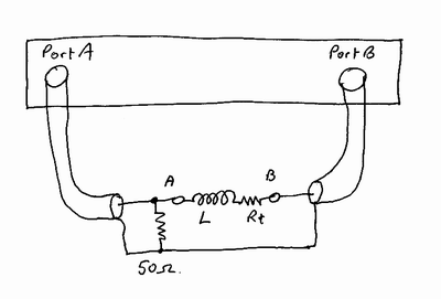
Firstly calibrate the VNA by lifting the two coax tails (from Points A&B) and connecting them together.
Then connect the choke between A & B and make a measurement of S21 Amplitude and Phase.
Then:
Zchoke = 50*(10^(-S21amp)/20) - 50
Rchoke = Zchoke*COS(-S21phase)
Xchoke = Zchoke*SIN(-S21phase)
The 2-port method gives more accurate results and can cope with much higher choke impedances.
73,
Steve G3TXQ
I just bought a Magnum S-6-175+. it came with a magnetic Wilson 1000 watter. I only tested it on the way back home in my Dodge Durango. It does work well with the Wil 1K but wanted to know some professionals opinions.
Also fill me in if dual antennas is better?
I will be slowly tweaking my system to get the most out of it as I can. Not looking to add another amp or anything just a good tweak on the radio.