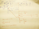
I am currently rebuilding my active probe and ruined the little internally-biased amplifier that compensated for the -20dB gain of the BF998 circuit. I figured I would use a BC848, but I don't design amps often and was hoping to have a second opinion before I put it together to make sure I did this right.
Thanks!
Goal for amplifier
The mosfet output has a DC offset of 1.38v, so subtracting the BJT's Vbe from that, I need 0.73v at the emitter. With 50mA of current, thats 14.6Ω (calling it 15Ω) for the emitter resistor. Since I need 50Ω output, I used 47Ω (its what I have) for the collector and bypassed the DC emitter resistance with 5Ω to set the RF voltage gain to 10. I planned on adding a small momentary switch to the housing so the circuit is only powered when taking readings.
Will this work? Did I do this right? Proposed changes in red ink:

Thanks!!!
Edit: I don't need a perfect 10x voltage gain. The problem is that when I have a 350mV pk-pk (or less) signal, my probe (with its -20dB output) provides only 35mV pk-pk to the FC through the 50Ω coax, the FC can't lock on an jumps around. I need at least 38mV pk-pk at the FC for it to count reliably.
Thanks!
Goal for amplifier
- have 20dB gain (voltage gain of 10x)
- have 50Ω output impedance
- not cook my little 100mA SMD regulator (draw 50mA or less as the BF998 part already takes 33mA)
- hoping to skip the base bias as the mosfet has a DC offset
The mosfet output has a DC offset of 1.38v, so subtracting the BJT's Vbe from that, I need 0.73v at the emitter. With 50mA of current, thats 14.6Ω (calling it 15Ω) for the emitter resistor. Since I need 50Ω output, I used 47Ω (its what I have) for the collector and bypassed the DC emitter resistance with 5Ω to set the RF voltage gain to 10. I planned on adding a small momentary switch to the housing so the circuit is only powered when taking readings.
Will this work? Did I do this right? Proposed changes in red ink:

Thanks!!!
Edit: I don't need a perfect 10x voltage gain. The problem is that when I have a 350mV pk-pk (or less) signal, my probe (with its -20dB output) provides only 35mV pk-pk to the FC through the 50Ω coax, the FC can't lock on an jumps around. I need at least 38mV pk-pk at the FC for it to count reliably.
Last edited:
