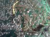
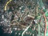
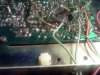
Replace the 11.1125 mhz crystal with a 11.3258 crystal. Locate PLL MB8719 chip right behind the channel selector.
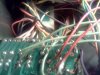
Isolate pin 10 from ground Cut all trace. Wire a switch from Pin 10 to ground and another from pin 11 to pin 12. You may need to re-align.
8719 channel chart Cobra 140 142 GTL
Position 1: Pin 10 down, 11-12 down
NORMAL CHANNELS
Position 2: Pin 10, Pin 11-12 down
15=26.815 20=26.885 25=26.925 30=26.985(ch3)
16=26.835 21=26.895 26=26.945 31=26.995(ch3A)
17=26.845 22=26.905 27=26.955 32=27.005(ch4)
18=26.855 23=26.935 28=26.965(ch1)
19=26.865 24=26.915 29=26.975(ch2)
Position 3: Pin 10 up, Pin 11-12 up
1=27.605 6=27.505 10=27.555 14=27.605
2=27.455 7=27.515 11=27.565 16=27.475
3=27.465 8=27.535 12=27.585 20=27.525
4=27.485 9=27.545 13=27.595 23=27.575
5=27.495
Position 4: Pin 10 down, Pin 11-12 up
1=27.605 11=27.725 21=27.855 31=27.955
2=27.615 12=27.745 22=27.865 32=27.965
3=27.625 13=27.755 23=27.895 33=27.975
4=27.645 14=27.765 24=27.875 34=27.985
5=27.655 15=27.775 25=27.885 35=27.995
6=27.665 16=27.795 26=27.905 36=28.005
7=27.675 17=27.805 27=27.915 37=28.015
8=27.695 18=27.815 28=27.925 38=28.025
9=27.705 19=27.825 29=27.935 39=28.035
10=27.715 20=27.845 30=27.945 40=28.045