
You are using an out of date browser. It may not display this or other websites correctly.
You should upgrade or use an alternative browser.
You should upgrade or use an alternative browser.
-
You can now help support WorldwideDX when you shop on Amazon at no additional cost to you! Simply follow this Shop on Amazon link first and a portion of any purchase is sent to WorldwideDX to help with site costs.
Cobra 148 gtl 1993 philly version
- Thread starter Staybolt
- Start date
If what you mean is to "lock" the transmit and receive frequencies together on that knob, it's really simple.
Stretching the coverage range of that control is a whole 'nother can of worms, but there are just two steps.
A diode that carries the transmit-only voltage to the PLL's clarifier circuit gets clipped or unsoldered.
A wire gets one end pulled from the circuit board behind the meter, where the receive-only voltage feeds the front-panel control.
The free end of this wire gets soldered to the continuous regulated 8 Volts DC, and makes the clarifier knob active on receive and transmit, both.
Gotta figure we have pics at my shop, or maybe a text file procedure.
I'll have a look when I get back to work. All those files are not "cloud" friendly, and can't read them from home.
73

Here is a procedure we settled on so long ago it never made it into any computer files, except for a few pictures. The Cobra 148GTL made in the Philippines between 1989 and about 1993 was the most-reliable and best-built of all the 148 radios of the last 40-plus years.
The procedure to "lock" the transmit and receive frequency together on the clarifier knob is probably the most-popular mod of all for this radio. We worked out the most-efficient way to do it so long ago it never got recorded as a computer file. Found some pics from a few years back that never got used. Found a junk Phil 148 and shot a couple more pics.
Just to start, this setup is correct for this circuit board, the PC-412. Wire colors won't be the same for other versions, so beware adapting to another 148 radio.
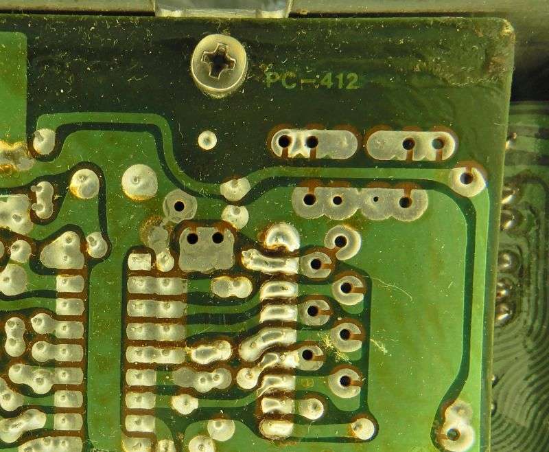
It's pretty simple. First step is to disable the transmit-only control of the radio's frequency. These two diodes, D75 and D52 are in series. Pulling one leg out of its hole on EITHER diode takes care of this step. Removing them completely is overkill, unless you will be hijacking them for carrier-control mod. Not covered here. All we need to do is break the series circuit of these two diodes.
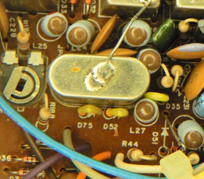
Next we need to identify the wire that powers the front-panel control. In the Philly 148 it's a white wire. Here is the end you DON'T disturb, next to R44.
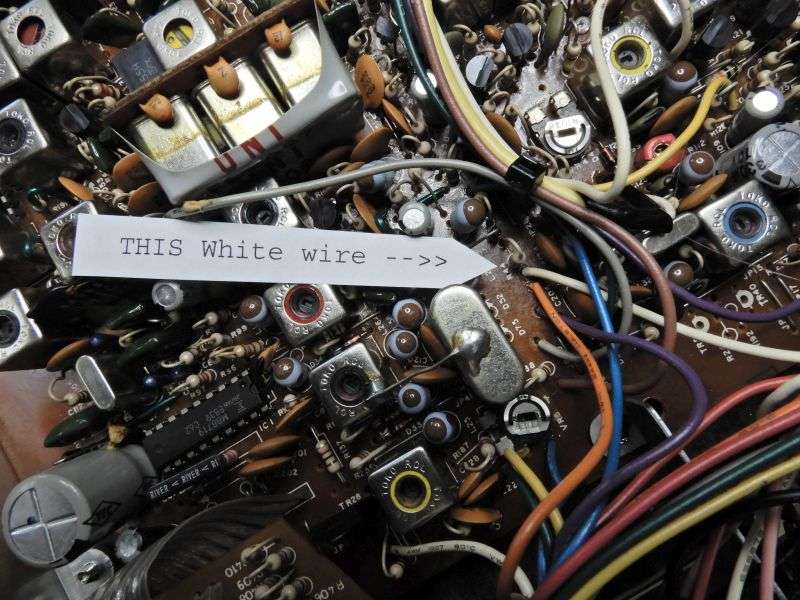
Here's another view. You don't mess with this end of the white wire, you follow it to the far end, behind the S-meter.

Here is where the white wire lands behind the S-meter, at the front end of VR3. Looks as if it's connected to VR3, BUT IT'S NOT. Just unsolder this wire and pull it out of the hole. Ignore the other white wires. You identified this one by following it from the hole next to R44, right?
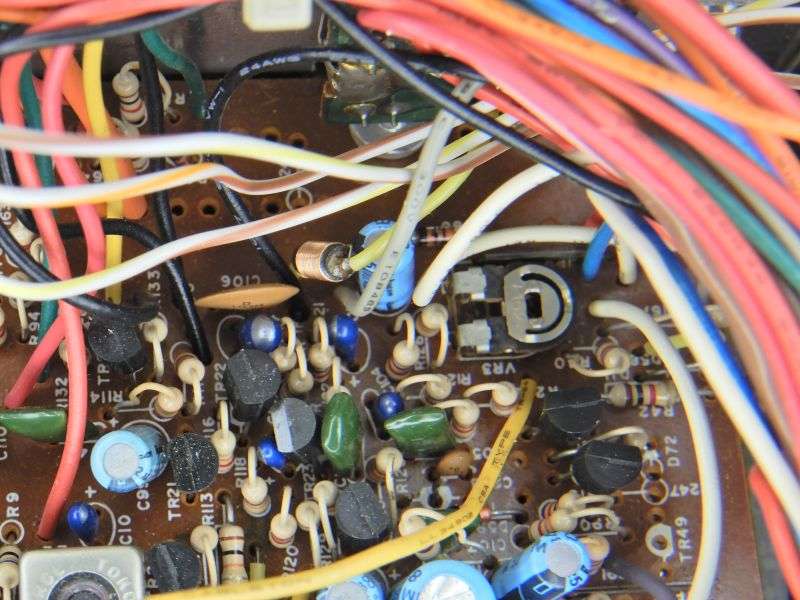
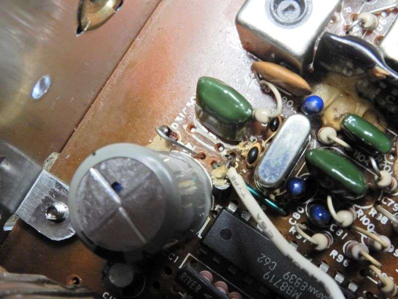
The now-free end of the white wire now connects to the regulated 8 Volts DC that powers the PLL circuit. Simplest place is the ferrite-bead choke feeding 8 Volts to pin 9 of the 8719 PLL chip. There is more than one place to obtain 8 Volts, so feel free to be creative. This is just the easiest spot to identify, that the wire will reach without splicing additional length onto it.
If the radio was already receiving on frequency, this won't change the clarifier knob's center-channel frequency.
And if what you wanted was to "stretch" the frequency range of the clarifier knob, you're on your own. That's not what this does.
73
The procedure to "lock" the transmit and receive frequency together on the clarifier knob is probably the most-popular mod of all for this radio. We worked out the most-efficient way to do it so long ago it never got recorded as a computer file. Found some pics from a few years back that never got used. Found a junk Phil 148 and shot a couple more pics.
Just to start, this setup is correct for this circuit board, the PC-412. Wire colors won't be the same for other versions, so beware adapting to another 148 radio.
It's pretty simple. First step is to disable the transmit-only control of the radio's frequency. These two diodes, D75 and D52 are in series. Pulling one leg out of its hole on EITHER diode takes care of this step. Removing them completely is overkill, unless you will be hijacking them for carrier-control mod. Not covered here. All we need to do is break the series circuit of these two diodes.
Next we need to identify the wire that powers the front-panel control. In the Philly 148 it's a white wire. Here is the end you DON'T disturb, next to R44.
Here's another view. You don't mess with this end of the white wire, you follow it to the far end, behind the S-meter.
Here is where the white wire lands behind the S-meter, at the front end of VR3. Looks as if it's connected to VR3, BUT IT'S NOT. Just unsolder this wire and pull it out of the hole. Ignore the other white wires. You identified this one by following it from the hole next to R44, right?
The now-free end of the white wire now connects to the regulated 8 Volts DC that powers the PLL circuit. Simplest place is the ferrite-bead choke feeding 8 Volts to pin 9 of the 8719 PLL chip. There is more than one place to obtain 8 Volts, so feel free to be creative. This is just the easiest spot to identify, that the wire will reach without splicing additional length onto it.
If the radio was already receiving on frequency, this won't change the clarifier knob's center-channel frequency.
And if what you wanted was to "stretch" the frequency range of the clarifier knob, you're on your own. That's not what this does.
73
I wasn't asking that, I was simply asking if it uses the same mod as the wires are different colors on the newer 148 clarifier pot. But thanks anyway.......Here is a procedure we settled on so long ago it never made it into any computer files, except for a few pictures. The Cobra 148GTL made in the Philippines between 1989 and about 1993 was the most-reliable and best-built of all the 148 radios of the last 40-plus years.
The procedure to "lock" the transmit and receive frequency together on the clarifier knob is probably the most-popular mod of all for this radio. We worked out the most-efficient way to do it so long ago it never got recorded as a computer file. Found some pics from a few years back that never got used. Found a junk Phil 148 and shot a couple more pics.
Just to start, this setup is correct for this circuit board, the PC-412. Wire colors won't be the same for other versions, so beware adapting to another 148 radio.
It's pretty simple. First step is to disable the transmit-only control of the radio's frequency. These two diodes, D75 and D52 are in series. Pulling one leg out of its hole on EITHER diode takes care of this step. Removing them completely is overkill, unless you will be hijacking them for carrier-control mod. Not covered here. All we need to do is break the series circuit of these two diodes.
Next we need to identify the wire that powers the front-panel control. In the Philly 148 it's a white wire. Here is the end you DON'T disturb, next to R44.
Here's another view. You don't mess with this end of the white wire, you follow it to the far end, behind the S-meter.
Here is where the white wire lands behind the S-meter, at the front end of VR3. Looks as if it's connected to VR3, BUT IT'S NOT. Just unsolder this wire and pull it out of the hole. Ignore the other white wires. You identified this one by following it from the hole next to R44, right?
The now-free end of the white wire now connects to the regulated 8 Volts DC that powers the PLL circuit. Simplest place is the ferrite-bead choke feeding 8 Volts to pin 9 of the 8719 PLL chip. There is more than one place to obtain 8 Volts, so feel free to be creative. This is just the easiest spot to identify, that the wire will reach without splicing additional length onto it.
If the radio was already receiving on frequency, this won't change the clarifier knob's center-channel frequency.
And if what you wanted was to "stretch" the frequency range of the clarifier knob, you're on your own. That's not what this does.
73
Appreciate that information. I have been meaning to do it to a radio for awhile. I just now have to go out and see if I can even find the thing lol.Here is a procedure we settled on so long ago it never made it into any computer files, except for a few pictures. The Cobra 148GTL made in the Philippines between 1989 and about 1993 was the most-reliable and best-built of all the 148 radios of the last 40-plus years.
The procedure to "lock" the transmit and receive frequency together on the clarifier knob is probably the most-popular mod of all for this radio. We worked out the most-efficient way to do it so long ago it never got recorded as a computer file. Found some pics from a few years back that never got used. Found a junk Phil 148 and shot a couple more pics.
Just to start, this setup is correct for this circuit board, the PC-412. Wire colors won't be the same for other versions, so beware adapting to another 148 radio.
It's pretty simple. First step is to disable the transmit-only control of the radio's frequency. These two diodes, D75 and D52 are in series. Pulling one leg out of its hole on EITHER diode takes care of this step. Removing them completely is overkill, unless you will be hijacking them for carrier-control mod. Not covered here. All we need to do is break the series circuit of these two diodes.
Next we need to identify the wire that powers the front-panel control. In the Philly 148 it's a white wire. Here is the end you DON'T disturb, next to R44.
Here's another view. You don't mess with this end of the white wire, you follow it to the far end, behind the S-meter.
Here is where the white wire lands behind the S-meter, at the front end of VR3. Looks as if it's connected to VR3, BUT IT'S NOT. Just unsolder this wire and pull it out of the hole. Ignore the other white wires. You identified this one by following it from the hole next to R44, right?
The now-free end of the white wire now connects to the regulated 8 Volts DC that powers the PLL circuit. Simplest place is the ferrite-bead choke feeding 8 Volts to pin 9 of the 8719 PLL chip. There is more than one place to obtain 8 Volts, so feel free to be creative. This is just the easiest spot to identify, that the wire will reach without splicing additional length onto it.
If the radio was already receiving on frequency, this won't change the clarifier knob's center-channel frequency.
And if what you wanted was to "stretch" the frequency range of the clarifier knob, you're on your own. That's not what this does.
73
Happy to report that it worked just fine. I shouldnt of installed a bigger physical sized capacitor from a couple years ago near the area where you soldered the wire to, but the wire had enough length to go under the board and back around to the point. It worked great. Thanks again. 
lol, been there done that.My bad on rude replies. I was a tad "lit" when I posted that.
Shadetree Mechanic
Delaware Base Station 808
Thanks Nomad, this is pure gold. I have an old 148 on the shelf that I have been neglecting. I have book marked this, maybe someday I will get around to it.Here is a procedure we settled on so long ago it never made it into any computer files, except for a few pictures. The Cobra 148GTL made in the Philippines between 1989 and about 1993 was the most-reliable and best-built of all the 148 radios of the last 40-plus years.
The procedure to "lock" the transmit and receive frequency together on the clarifier knob is probably the most-popular mod of all for this radio. We worked out the most-efficient way to do it so long ago it never got recorded as a computer file. Found some pics from a few years back that never got used. Found a junk Phil 148 and shot a couple more pics.
Just to start, this setup is correct for this circuit board, the PC-412. Wire colors won't be the same for other versions, so beware adapting to another 148 radio.
It's pretty simple. First step is to disable the transmit-only control of the radio's frequency. These two diodes, D75 and D52 are in series. Pulling one leg out of its hole on EITHER diode takes care of this step. Removing them completely is overkill, unless you will be hijacking them for carrier-control mod. Not covered here. All we need to do is break the series circuit of these two diodes.
Next we need to identify the wire that powers the front-panel control. In the Philly 148 it's a white wire. Here is the end you DON'T disturb, next to R44.
Here's another view. You don't mess with this end of the white wire, you follow it to the far end, behind the S-meter.
Here is where the white wire lands behind the S-meter, at the front end of VR3. Looks as if it's connected to VR3, BUT IT'S NOT. Just unsolder this wire and pull it out of the hole. Ignore the other white wires. You identified this one by following it from the hole next to R44, right?
The now-free end of the white wire now connects to the regulated 8 Volts DC that powers the PLL circuit. Simplest place is the ferrite-bead choke feeding 8 Volts to pin 9 of the 8719 PLL chip. There is more than one place to obtain 8 Volts, so feel free to be creative. This is just the easiest spot to identify, that the wire will reach without splicing additional length onto it.
If the radio was already receiving on frequency, this won't change the clarifier knob's center-channel frequency.
And if what you wanted was to "stretch" the frequency range of the clarifier knob, you're on your own. That's not what this does.
73
Oh yeah, this is getting printed and put in the binder. My binders are full of words of wisdom from these guys. You can't find better information on things like this anywhere except here. Good stuff on this forum, to the very last drop. I'll take a refill please and thank you.Here is a procedure we settled on so long ago it never made it into any computer files, except for a few pictures. The Cobra 148GTL made in the Philippines between 1989 and about 1993 was the most-reliable and best-built of all the 148 radios of the last 40-plus years.
The procedure to "lock" the transmit and receive frequency together on the clarifier knob is probably the most-popular mod of all for this radio. We worked out the most-efficient way to do it so long ago it never got recorded as a computer file. Found some pics from a few years back that never got used. Found a junk Phil 148 and shot a couple more pics.
Just to start, this setup is correct for this circuit board, the PC-412. Wire colors won't be the same for other versions, so beware adapting to another 148 radio.
It's pretty simple. First step is to disable the transmit-only control of the radio's frequency. These two diodes, D75 and D52 are in series. Pulling one leg out of its hole on EITHER diode takes care of this step. Removing them completely is overkill, unless you will be hijacking them for carrier-control mod. Not covered here. All we need to do is break the series circuit of these two diodes.
Next we need to identify the wire that powers the front-panel control. In the Philly 148 it's a white wire. Here is the end you DON'T disturb, next to R44.
Here's another view. You don't mess with this end of the white wire, you follow it to the far end, behind the S-meter.
Here is where the white wire lands behind the S-meter, at the front end of VR3. Looks as if it's connected to VR3, BUT IT'S NOT. Just unsolder this wire and pull it out of the hole. Ignore the other white wires. You identified this one by following it from the hole next to R44, right?
The now-free end of the white wire now connects to the regulated 8 Volts DC that powers the PLL circuit. Simplest place is the ferrite-bead choke feeding 8 Volts to pin 9 of the 8719 PLL chip. There is more than one place to obtain 8 Volts, so feel free to be creative. This is just the easiest spot to identify, that the wire will reach without splicing additional length onto it.
If the radio was already receiving on frequency, this won't change the clarifier knob's center-channel frequency.
And if what you wanted was to "stretch" the frequency range of the clarifier knob, you're on your own. That's not what this does.
73
I like that idea... A binder with some good information.Oh yeah, this is getting printed and put in the binder. My binders are full of words of wisdom from these guys. You can't find better information on things like this anywhere except here. Good stuff on this forum, to the very last drop. I'll take a refill please and thank you.
I'm still waiting for the forum to sell archive copies of the forum content. If they had two download options, the entire forum as one option and the past year as an end-of-year archive update for the other option, I'd be downloading it each year.
Maybe one day @AudioShockwav will make it happen. I'd gladly pay.
Shadetree Mechanic
Delaware Base Station 808
dxChat
- No one is chatting at the moment.
-
-
-
dxBot:63Sprint has left the room.
-
dxBot:kennyjames 0151 has left the room.
-