The mount, whether it's a 'puck' or some other kind, is to merely furnish a way to hold an antenna in a particular place in a particular way. If it does that as it should, then it's the proper mount for that antenna. There are quite a few that can do the same thing, just different 'styles'.
That impedance matching coil is only there to change one impedance to another impedance by adding inductive reactance between the 'hot' antenna and ground. It can also be of several different shapes/sizes and mounting positions, as long as it adds the right amount of reactance in the right place.
Can that impedance matching coil be enclosed? Sure, it is very common for that coil to be placed in some type of enclosure, it just depends on the size of that coil and how it's made. An adjustable coil is a bit more difficult to enclose because you have to be able to get to it to do any adjusting. (That holds true for loading coils too, BTW. More a convenience thing instead of "impossible" to do.) If that coil is not adjustable, then it's much easier to put it inside of some enclosure since you don't have to 'get to it'.
Will enclosing a coil change it's inductance? It can, but if the 'size' of the inductance is picked right, then things work just fine. (Transformers are coils, enclosing those coils it about as common as it gets, right?)
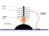
There's no minimum height requirement for an impedance matching coil, or any maximum height requirement, other than the thing has to be of a particular size to produce the required inductance. The thing is connected from ground to the 'hot' of the antenna. There has to be enough space to allow there to be some insulation to keep the 'hot' from grounding out to start with, but that matching coil will bridge that insulator, that's why it works. There's no particular 'size' requirement for the mount. It's a 'mechanical' thingy, it's got to get from one side of an insulator tot he other and not flop around a lot.
So why would a 'puck' mount be too small/short?
- 'Doc