• You can now help support WorldwideDX when you shop on Amazon at no additional cost to you! Simply follow this Shop on Amazon link first and a portion of any purchase is sent to WorldwideDX to help with site costs.

Looking for Help (Bias Adjustment)

Hit and Run

Member
Sep 5, 2010
3
0
11
I hope someone out here can help me out.

I have come across a Dave Made Tube Amp using 4-4CX250B tubes. The front of the amp has a variable bias adjustment. Before I damage something, can anyone provide me the proper bias adjustment procedures for this amp?

Thanks for all and anyone's help.
 

I hope someone out here can help me out.

I have come across a Dave Made Tube Amp using 4-4CX250B tubes. The front of the amp has a variable bias adjustment. Before I damage something, can anyone provide me the proper bias adjustment procedures for this amp?

Thanks for all and anyone's help.

I gonna be hard pressed to give you an accurate answer because, there are many variables that are unknown.

First and foremost, the idea on placing the bias outboard on that type on amp was lame-brained; those are tubes whos' class of operation is fixed by the amount of Screen volts and the amount of Negative Bias volts on the tube.

Is this amplifier "Grid-driven" or Cathode driven? Can you post so detailed pictures of the inside of the amp?

Ballpark answer, -35 to -50 volts, set in idle condition (no RF drive, amplifier in transmit position).

That tube has at least 2000 volts on the plate, maybe +300 vdc on the screens and -50 volts on the bias circuit, put your hand in the wrong place and, you will learn a lesson hopefully, we will not be reading about you, Be Careful

.
 
Some of these guys are driving the grids on the 4CX250B's. If the drive requirements are over 75 watts it's probably a grounded triode amp. If the drive requirements are less then 20 watts it's a grid driven tetrode. I've seen cases where they didn't even neutralize the amp and just swamp the heck out of the control grids with shunt resistors. Don't even ask about screen regulation. Most exceed the rated anode voltage so they can claim multiple kilowatts from four tubes. Few hang onto their matched set of tubes long or can handle the extra 400 milliamps required to put the four tubes into class AB1. Dave's may be better but to get an idea would require pictures.
 
For 1000 watts plate dissipation in triode configuration you might as well just use a pair of 3-500Z's. So, Hit and Run, do tell us what the drive requirements are on this amplifier for full output? Unless the amplifier has a CALIBRATED plate current meter, aligning the bias for a particular class of operation would involve having to measure dangerous points within the amp. Not recommended. If you're lucky enough to have an accurate front panel plate current meter, the bias would be set at 400 ma with the relay keyed and no drive applied. This gives you the 100 ma per tube (assuming they are matched) for class AB1.

If the plate voltage is more then about 2000 volts under load or you use the amp on AM, I would seriously consider a lot less bias on these tubes. Most CB amps are already stressed out to the max to begin with. Adding 800 watts of DC bias dissipation on the plates for AB1 may well push the amp over the edge and start burning things up. If I were you I would put the amp in class B at no more then half the AB1 bias current. I'd keep all four tubes at or below 200 ma total zero signal bias current. The bias current would be the same if it were grid driven or cathode driven. But, how many watts drive does it take?
 
Let me see if I can answer some questions for you all.

This amp (what I was told) uses a 4-5 watt carrier. The radio to be used will have a 40 watts peak modulation drive. I was told this is fine for the 4CX250B tubes.

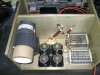
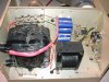
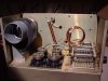
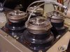
When the amp was acquired it came with a bag with four resistors in it. I was told these were soldered to the tube clamps, all four tied together and a single lead went to a door knob capaciator. The resistors are 10 ohm, 5% carbon composition resistors. Not sure what the watt rating is, thinking it may be 2-5 watt rating. The resistors have a single wire wrapping three times around the resistors and soldered on both ends. What is the reason for this and is this a shunt resistor as someonen else mentioned? Looking at the resistors, they have been overheated pretty bad and I guess the guy who had it was going to replace them.

I searched the web for pictures of the amp and found some which I will include. The amp I found on the web does not use the resistors from the tube clamps to the door knob capactor. It is a solid braid lead from each tube to the capaciator. What is the impact or reason for removing the resistors? With this damage the amp not having this protection?

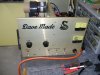
The amp have two meters on the front, one is a KV meter and the other is a AMP meter. The knob on the bottom right is the bias control. Which meter is to be adjust, the AMP or KV meter? Now looking at the face of the meter, it suggest that these are not premium grade meters so I assume accuracy is not the greatest. There are a couple setting to set the bias to, between -35 to -50 (is this per tube?) or -400 (all four combined -100 per tube)? Your thoughts. KV Volts read at 2100 to 2200.

I appologize for all the questions, but where I am at there is no one capable to work on this sort of equipment. I also live far enough away from everything that shipping would be an arm and a leg. So I have accepted the challange to figure this out on my own and hopefully with all your help, be successful.

Thanks everyone and if you have additional questions or information you need, let me knnow.
 

Attachments

  • 4CX250B DSC01136.JPG
    4CX250B DSC01136.JPG
    174.8 KB · Views: 1,538
  • 4CX250B DSC01137.JPG
    4CX250B DSC01137.JPG
    162.5 KB · Views: 497
  • 4CX250B DSC00019.jpg
    4CX250B DSC00019.jpg
    123.6 KB · Views: 440
  • WEB Photo DSC00012.jpg
    WEB Photo DSC00012.jpg
    98.1 KB · Views: 403
  • WEB Photo DSC00018.jpg
    WEB Photo DSC00018.jpg
    106.4 KB · Views: 522
The 4 or 5 watt carrier drive says tetrode but the pictures say triode. I don't see any signs of a screen supply, neutralization, or screen regulator. There is the slightest chance there could be a screen winding on one of those transformers with the rectifiers and filter caps on the bottom but I doubt it.

The resistors with the coil around them are called parasitic suppressors. They help stabilize the amplifier so it's more resistant to oscillations. Some of which can be destructive to the tubes. It's a smart idea to include them on this tube at this frequency. The resistors are usually 33 to 100 ohms at 2 watts, carbon.

The bias should be set to the amp meter. I recommend 200 milliamps or less for the total four tubes. This is 0.2 amps set with the relay keyed and no drive applied. This is around class B and probably going to be your safest bet. Class AB1 would be 0.4 amps for all four tubes total and that might be risky.
 
Shockwave,

Thank you for the quick response to my last post. You have answered all my questions thus far. If you were to choose, what ohm resistor would you go with? Does it really make that much of a difference? The band color code on the original resistor is Brown, Black, Black, Gold. Again, your thoughts and reasoning.....

I figured the wattage of the resistor should be 2 watts from what I read on the tube data sheet, but wasn't for sure..

Thanks again for your help and I will check back shortly before hunting down any parts. If you have other recommendations for this amp, please let me know.
 
The design of the parasitic suppressor is dependant on the tube used and the frequency used. I would think 47 ohms with 3 or 4 turn of # 16 wire loosely wrapped should work in this application. Getting the wire right is more important then the resistance as long as the value is between 33 and 100 ohms. The selection of 2 watt carbon resistors is very limited today. You might need eBay for this.
 
Bottom of Tube Sockets

Hows' about some pictures of the inside of the RF Deck showing the wiring of the tube sockets and associated circuitry?

.
 
That amp is so pretty, I'd be terrified of messing it up. You should call Dave and ask him. Try and keep it original. DAVEMADE .com - Home

For those of you that were wondering how that all works. When I built amps before, we generally decided on a bias voltage during the design and change our minds during the fine tuning. The final decision is based on the cleanest looking sine wave, assuming that the power limit would be fixed by the running temperature of the parts. I assume that manufacturers have always done it the same way, there are simply too many variables to nail it perfectly in any practical or cost effective manner. I also assume that companys like Dave Made, write the bias that they decided was best in their notes, afterall, we we just a bunch of guys, building cost effective amps for our own use, with a home brewed signal generator and a borrowed o-scope, and we thought to.
 

dxChat
Help Users
  • No one is chatting at the moment.